Flexible protective guide internally holding long members

a protective guide and flexible technology, applied in the direction of hoisting chains, cable arrangements between relatively moving parts, etc., can solve the problems of difficult manufacturing, mutual noise caused by link plates, dust produced, etc., and achieve the effect of smooth cable guide, easy response and good versatility

Inactive Publication Date: 2015-10-20
DENSO WAVE INC +1
View PDF37 Cites 18 Cited by
  • Summary
  • Abstract
  • Description
  • Claims
  • Application Information

AI Technical Summary

Benefits of technology

[0010]Thus it is desired to provide a protective guide for cables and / or ducts, which eliminates such bothersome works as assembling link plates, reduces dust, bending noise and bending vibration, easily copes with movement strokes of various lengths, and smoothly holds and guides the cables and / or ducts without causing a backlash not only in a linear-posture guiding portion but also in a bent-posture guiding portion.
[0013]In the protective guide, while the bent portion changes its position with the movement of the movable member, a new portion of the protective guide in a linear posture changes into a bent posture, while a portion of the protective guide that has been in the bent posture returns to the linear posture. When the protective guide turns into the bent posture, the curve in the curved strip-shaped base is flattened, while gaps (e.g., slits) in between the plurality of sectioning members that are positioned in the bent portion each become wider, little by little, than the original width. Distortion (or strain) that would be caused when the linear posture turns into the bent posture is absorbed by the flattening of the strip-shaped base and the widening of the gaps in between the plurality of sectioning members. Thus, the space for accommodating the cables is reliably ensured in both of the linear- and bent-posture portions of the protective guide. In this way, the protective guide is able to smoothly guide the cables without causing a backlash not only in the linear-posture guiding portion but also in the bent-posture guiding portion.
[0014]Further, since the long protective guide is made of a resinous material and thus has flexibility, the assembling works, for example, of link plates as in the conventional art is no longer necessary. Also, not using link plates that are brought into contact with each other in guiding the cables can eliminate such problems as producing dust and causing bending noise and bending vibration during the guiding. In addition, a protective guide of a desired length is obtained by only cutting off the protective guide at a position in the longitudinal direction in conformity with the stroke of the movable member of the machine in which the protective guide is installed. Thus, the protective guide is able to easily respond to the applications in which the protective guide is required to have various lengths, thereby providing a good versatility.

Problems solved by technology

However, in exchange of the possible elongation by assembling the link plates, such an assembled cable protective guide chain involves lots of work in assembling the link plates, the flaps and the bottom plates.
Further, when such an assembled cable protective guide chain is used, dust may be produced due to the friction between the link plates.
In addition, when such an assembled cable protective guide chain is bent, noise may be mutually caused by the link plates.
Also, such an assembled cable protective guide chain may cause vibration due to the mutual polygonal action of the link plates.
Therefore, the foldable cable protective member, when it is applied such as to a linear actuator machine having a long movement stroke, is very often difficult to manufacture with the length suitable for the long movement stroke.
For example, there is a physical limitation in the size of the die used for injection molding.
Further, since a desired movement stroke is different between the users, providing a plurality of dies suitable for the individual desired movement strokes invites increase in the manufacturing cost.

Method used


Image

  • Flexible protective guide internally holding long members
  • Flexible protective guide internally holding long members
  • Flexible protective guide internally holding long members

Examples


Embodiment Construction

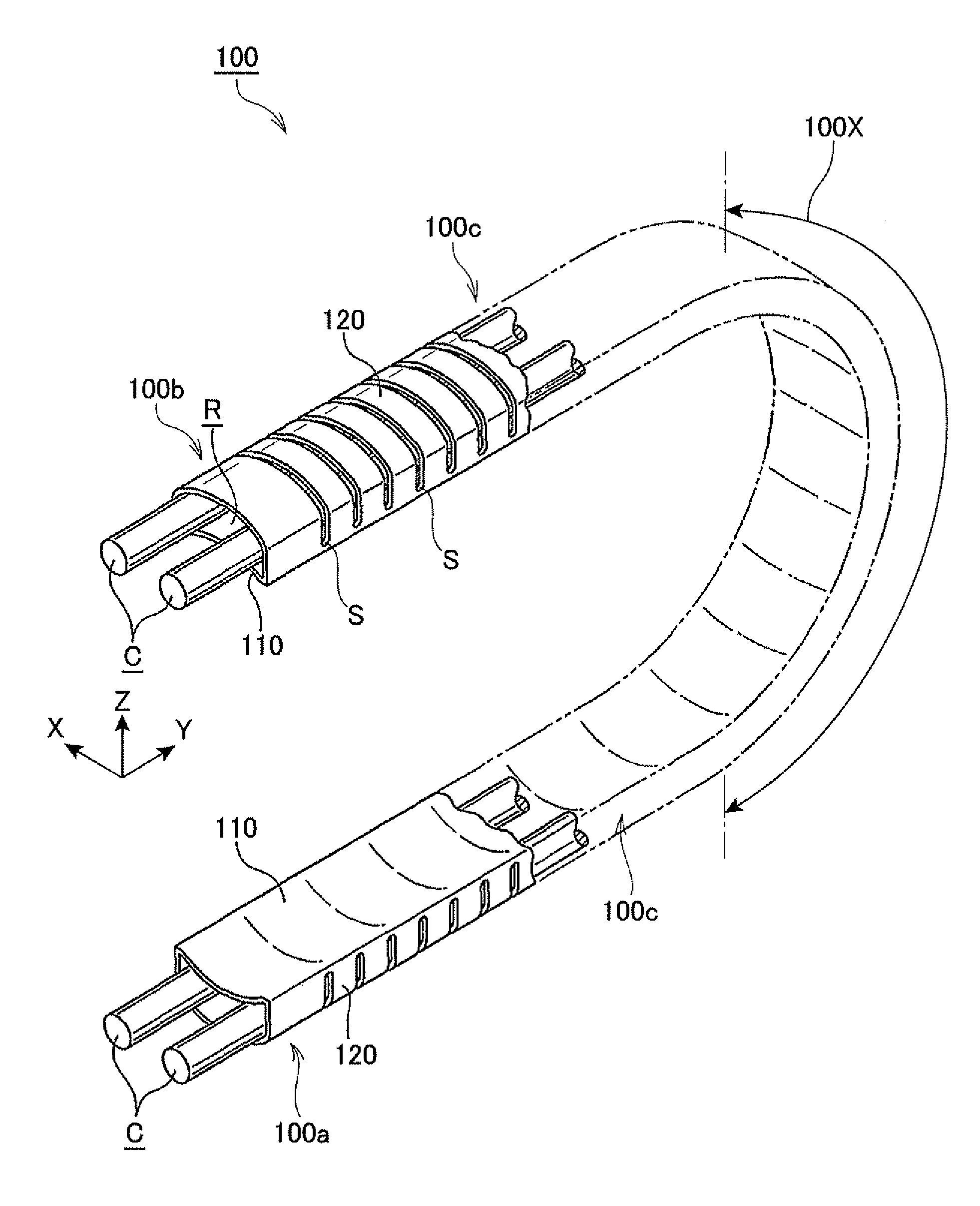
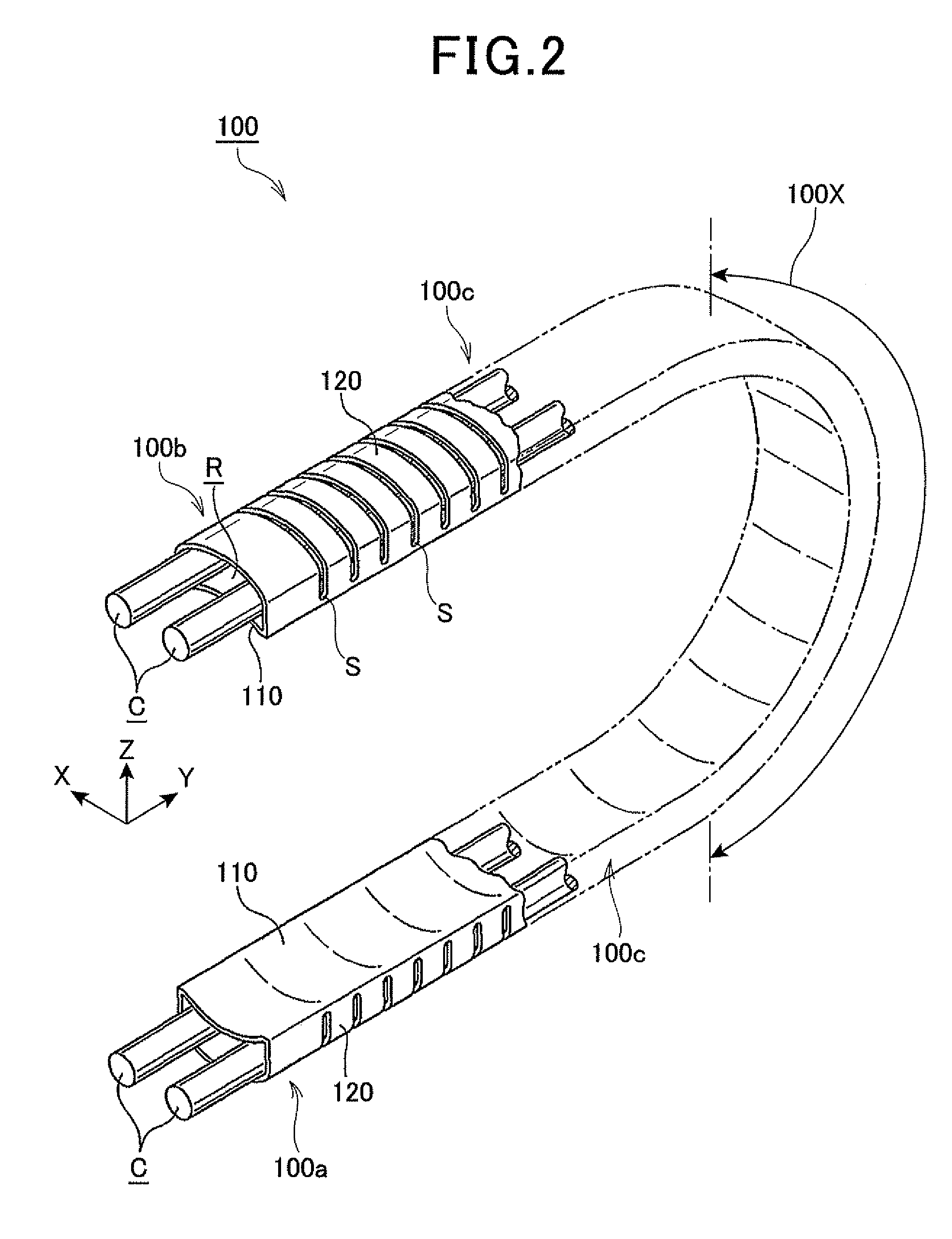
[0026]With reference to FIGS. 1 to 8, hereinafter is described an embodiment of a cable protective guide made of a synthetic resin, according to an embodiment of the present invention.

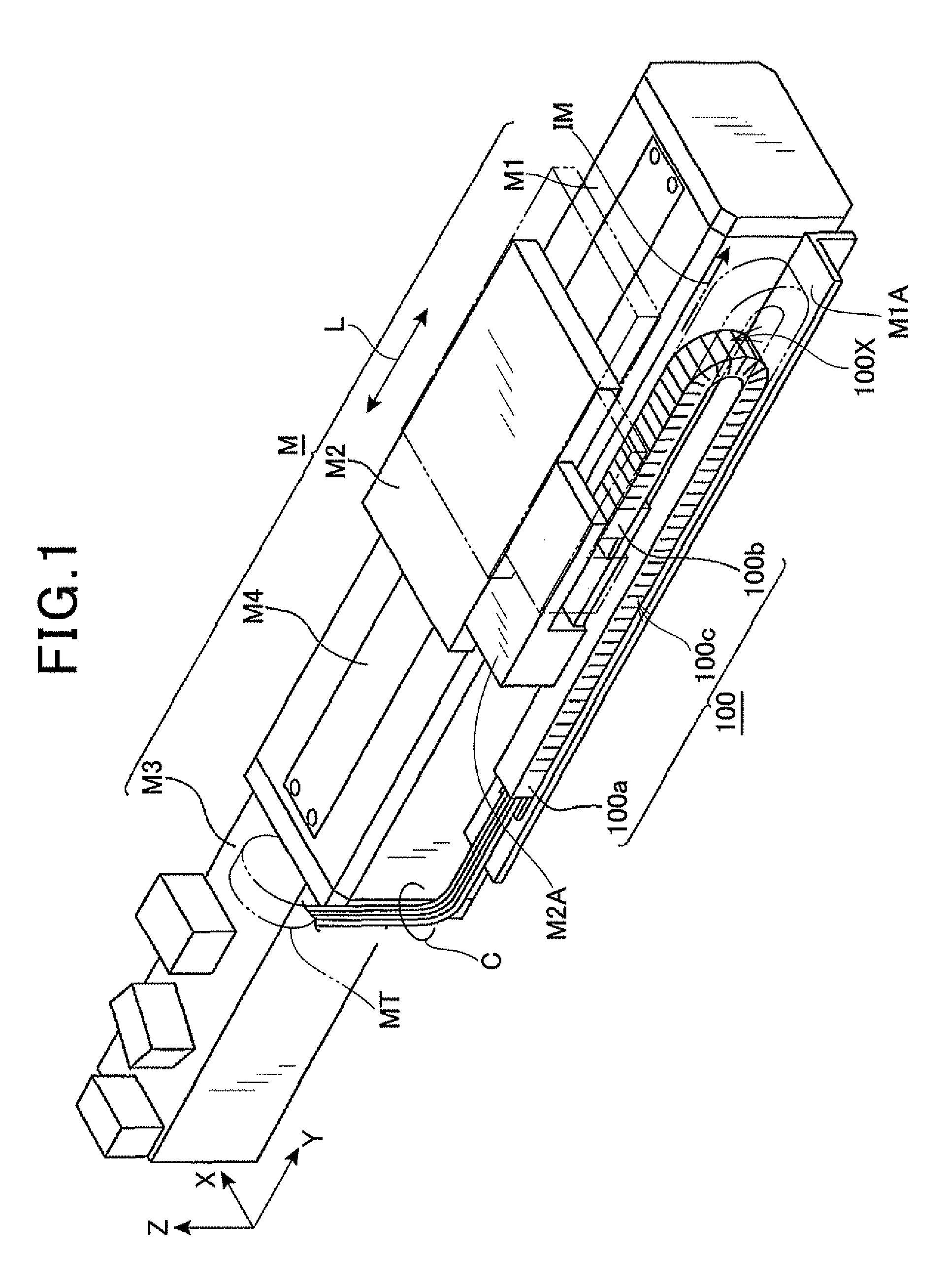
[0027]FIG. 1 is a perspective view illustrating a linear movement device M called a linear robot mounting a cable protective guide 100 according to the present embodiment.

[0028]The linear movement device M incorporates a ball-screw driven actuator. Specifically, as shown in FIG. 1, the linear movement device M includes a fixed frame M1, a movable member M2, a setting frame M3 and an actuator M4. The fixed frame M1 is provided on a machine side. The movable member M2 is a movable frame provided on the machine side. The setting frame M3 is connected to the fixed frame M1 and incorporates a drive motor MT. The actuator M4 is a ball-screw driven actuator for linearly moving the movable member M2 with respect to the fixed frame M1. Upon rotation of the drive motor MT incorporated in the setting frame M3, th...


PUM


Abstract

A protective guide has a long shape and internally holds long members including at least one of flexible cables and ducts. The protective guide includes a flexible curved strip-shaped base and a plurality of flexible sectioning members. The base is made of a synthetic resin, formed into a long plate and has a longitudinal direction. The sectioning members are also made of a synthetic resin, permitted to uprise from both ends of the base and spaced apart from each other in the longitudinal direction, the both ends being opposed to each other in a direction perpendicular to the longitudinal direction. The sectioning members cooperatively define a space for accommodating the long members along the base. The base has a cross section inwardly curved toward the space, as viewed in the longitudinal direction.

Description

CROSS-REFERENCE TO RELATED APPLICATION[0001]This application is based on and claims the benefit of priority from earlier Japanese Patent Application No. 2011-208573 filed Sep. 26, 2011, the description of which is incorporated herein by reference.BACKGROUND OF THE INVENTION[0002]1. Technical Field of the Invention[0003]The present invention relates to a flexible protective guide for internally holding long flexible cables and / or ducts and guiding their behaviors to a given path, while protecting the cables and / or ducts, the cables and / or ducts connecting a fixed side of a machine in which the cable protective guide is installed to a movable side of the machine to transmit electrical signals therebetween or transfer a physical medium therebetween. In particular, the present invention relates to a long flexible protective guide preferable for an application in which cables and / or ducts are bent for connection between a fixed side of a machine in which the cable protective guide is ins...

Claims


Application Information

Patent Timeline
Patent Type & Authority Patents(United States)
IPC IPC(8): F16L3/015F16G13/16H02G3/04H02G11/00
CPCF16G13/16H02G3/0487H02G11/006H02G3/04
Inventor KAIHOTSU, KOUICHIBANNO, WATARUHIGASHINO, TAKESHI
Owner DENSO WAVE INC
Why Eureka
Try Eureka