Coaxial electric connector
a technology of electric connectors and coaxial plates, applied in the direction of telephony connectors, electrical devices, connections, etc., can solve the problems of becoming difficult to maintain good high-frequency characteristics, and achieve the effect of reducing the dielectric constant, reducing and not increasing the thickness of the shell cover par
- Summary
- Abstract
- Description
- Claims
- Application Information
AI Technical Summary
Benefits of technology
Problems solved by technology
Method used
Image
Examples
first embodiment
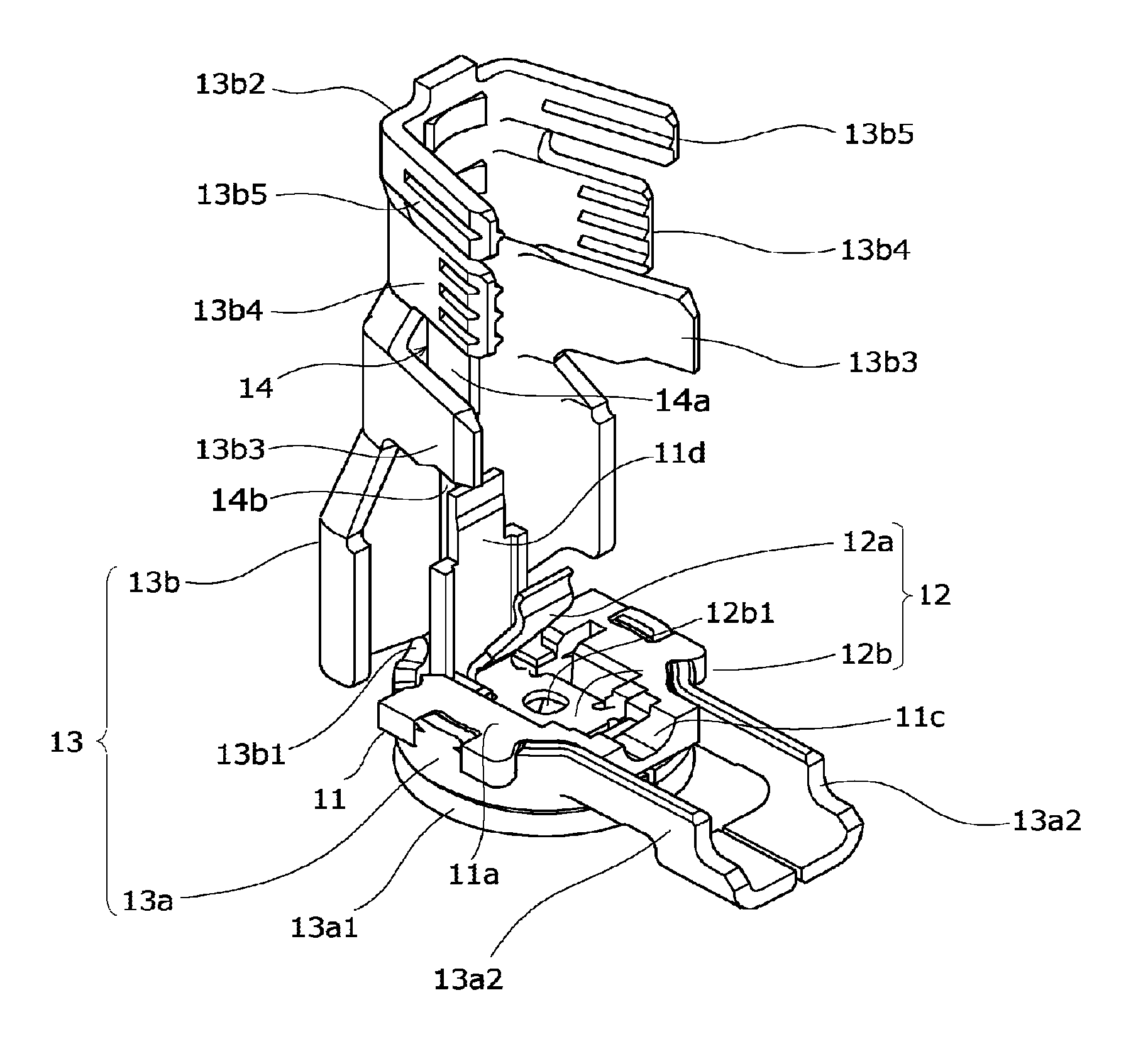
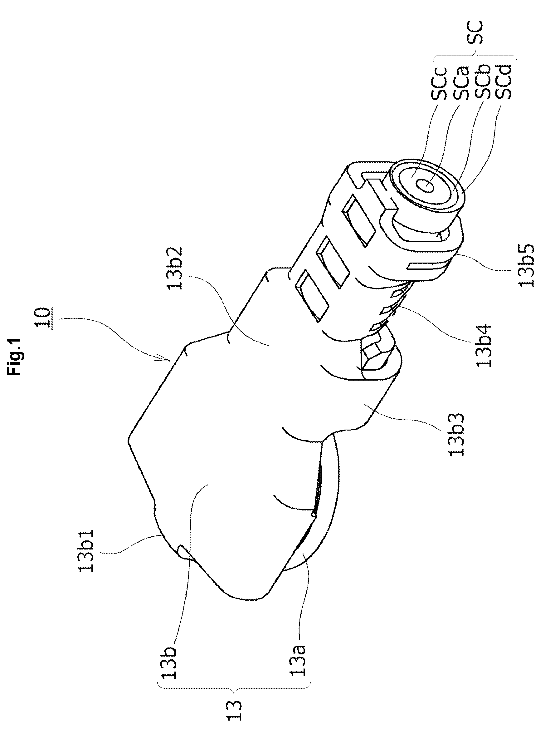
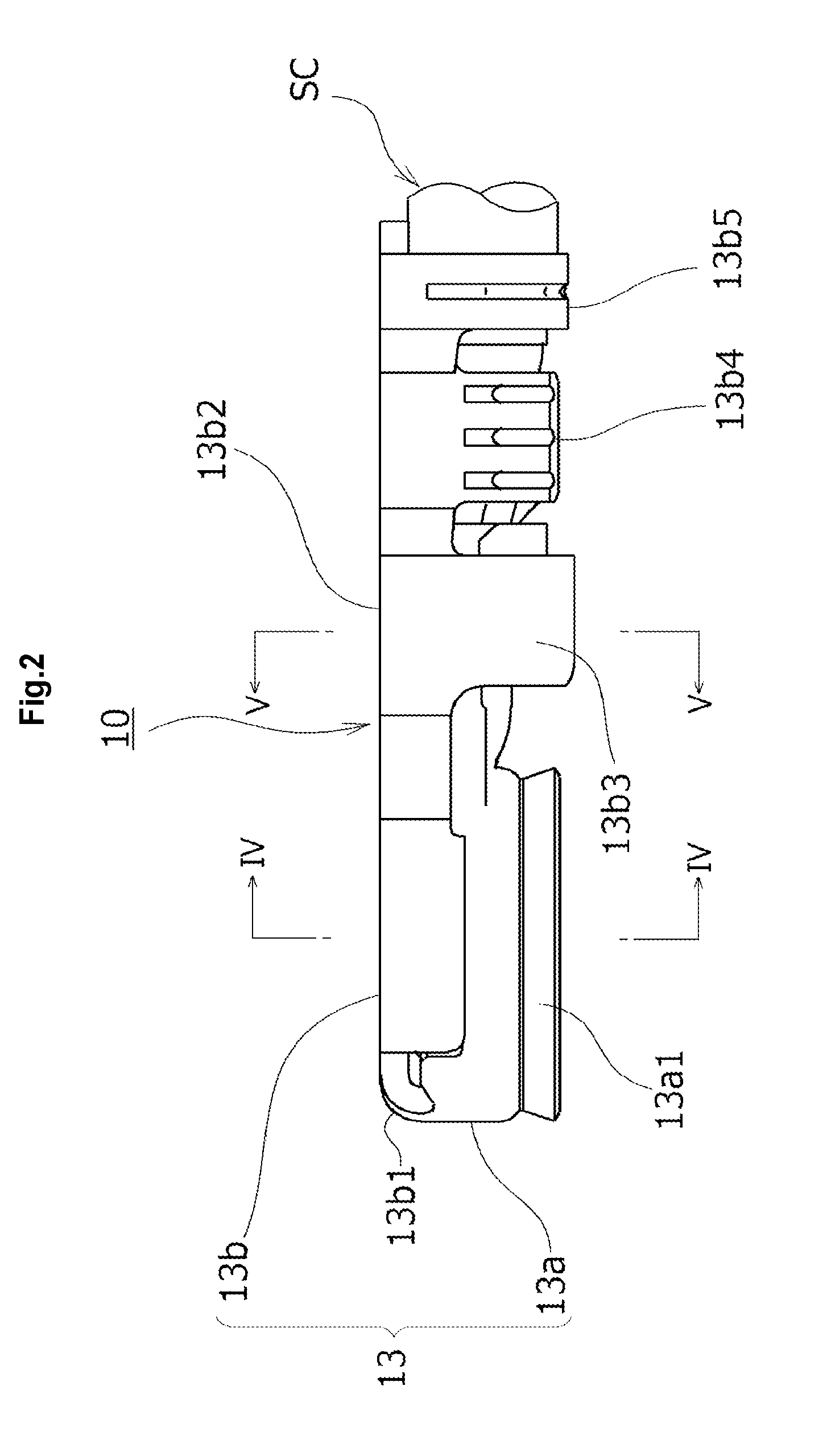
[0053]First, a plug connector 10 serving as a coaxial electric connector according to the present invention shown in FIG. 1 to FIG. 6 is configured to be coupled to a terminal part of a thin coaxial cable SC serving as a cable-shaped signal transmission medium and is configured to be mated so as to be inserted from the upper side to or removed from a mating electric connector (illustration omitted) consisting of, for example, a receptacle connector mounted on a predetermined printed wiring board, of which illustration is omitted. A mating / removing operation of the plug connector 10 with respect to the mating electric connector (for example, receptacle connector) is carried out in a direction approximately orthogonal to the plane of the printed wiring board.
[0054]More specifically, a connector main-body part constituting a main mating part of the plug connector 10 is formed so as to form a cylindrical shape as a rough shape, a terminal part of the thin coaxial cable SC is coupled to ...
eighth embodiment
[0081]The void part 14 in the present embodiment is formed by an inner wall surface of a recessed groove-shaped part which is a partial dent of the inner surface of the shell cover part 13b. The recessed groove-shaped part constituting the void part 14 is formed, for example, by pressing and is provided by reducing the plate thickness of the shell cover part 13b by the groove depth of the recessed groove-shaped part constituting the void part 14. The recessed groove-shaped part constituting the void part 14 is provided by separating at least one of the cover inner surface of the shell cover part 13b and the insulative pressing plate 11d from the other one. Like an eighth embodiment which will be described later, the recessed groove-shaped part constituting the void part may be provided on the insulative pressing plate 11d, or recessed groove-shaped parts constituting a void part can be provided on the both members.
[0082]As described above, the recessed groove-shaped part constitutin...
sixth embodiment
[0100]On the other hand, in a sixth embodiment according to FIG. 21 and FIG. 22 in which the same constituent members as those of the above described embodiments are denoted by the same reference signs, a pair of recessed groove-shaped parts 14g and 14g extended in the connector left-right direction are formed on the cover inner surface of the shell cover part 13b1 so as to form the void part 14 positioned above the cable center conductor SCa of the thin coaxial cable SC. Each of the recessed groove-shaped parts 14g of the present embodiment has a groove width somewhat larger than that of the insulative pressing plate 11d, and most part of the surface of the insulative pressing plate 11d is configured to be received by the cover inner surface of the shell cover part 13b1. Therefore, the insulative pressing plate 11d does not enter the interior of the recessed groove-shaped parts 14g of the void part 14, and the void part 14 is configured to be formed by the recessed groove-shaped pa...
PUM
 Abstract
Description
Claims
Application Information
 - R&D
- Intellectual Property
- Life Sciences
- Materials
- Tech Scout
- Unparalleled Data Quality
- Higher Quality Content
- 60% Fewer Hallucinations
Browse by: Latest US Patents, China's latest patents, Technical Efficacy Thesaurus, Application Domain, Technology Topic, Popular Technical Reports.
© 2025 PatSnap. All rights reserved.Legal|Privacy policy|Modern Slavery Act Transparency Statement|Sitemap|About US| Contact US: help@patsnap.com


