Driver Circuit for Discrete High Power IGBT

A bipolar transistor and driving circuit technology, applied in the direction of output power conversion devices, electrical components, etc., can solve problems such as IGBT application circuits that are not suitable for higher power

Inactive Publication Date: 2016-07-06
XIDIAN UNIV
View PDF3 Cites 0 Cited by
  • Summary
  • Abstract
  • Description
  • Claims
  • Application Information

AI Technical Summary

Problems solved by technology

However, since this dedicated integrated drive circuit can only drive IGBT devices with very low collector and emitter voltages, for example, IR's IR2130 can only be used to drive IGBTs with a voltage not exceeding 600V, which makes this type of drive The circuit is not suitable for higher power IGBT application circuits

Method used


Image

  • Driver Circuit for Discrete High Power IGBT
  • Driver Circuit for Discrete High Power IGBT
  • Driver Circuit for Discrete High Power IGBT

Examples


Embodiment Construction

[0031] The present invention will be further described below in conjunction with accompanying drawings and embodiments thereof.

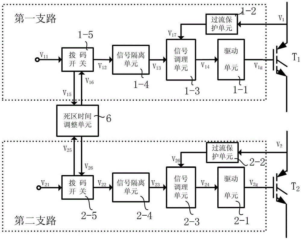
[0032] refer to figure 1 , the present invention includes upper and lower two groups of completely identical branches, each branch includes a drive unit 1, an overcurrent protection unit 2, a signal conditioning unit 3, a signal isolation unit 4 and a dial switch 5, and the dial switches of the two branches A dead-time adjustment unit 6 is connected between the switches.

[0033] The transmission relationship of the first branch is:

[0034] DIP switch 1-5, receiving microprocessor input control voltage signal V 11 , and the voltage signal V 12 To the output to the signal isolation unit 1-4;

[0035] Signal isolation unit 1-4 for output and input voltage signal V 12 phase opposite voltage signal V 13 to the signal conditioning unit 1-3, and the output signal V 13 with the received voltage signal V 12 The voltage signal is electrically isolat...


PUM


Abstract

The invention relates to a driving circuit for a separating type high-power IGBT (Insulated Gate Bipolar Transistor). The driving circuit comprises two groups of branch circuits with same structures in the upper part and the lower part, wherein each branch circuit comprises a driving unit (1), a signal conditioning unit (3), a signal isolating unit (4) and a dial switch (5) which are sequentially connected; a current protection unit (2) is connected between one end of each signal conditioning unit (3) and a collector electrode of a controlled IGBT in a crossing way; a dead time adjusting unit (6) is connected between the dial switches (5) of the two branch circuits; each signal isolating unit (4) adopts a digital optical coupler for realizing the electrical isolation on a primary side signal and an auxiliary side signal of the digital optical coupler; the working mode of the driving circuit disclosed by the invention is set by the dial switches (5); the dead time adjusting unit (6) is used for supplying dead time to the driving circuit when the driving circuit works in a half-bridge circuit mode. The driving circuit disclosed by the invention has the advantages of high isolation voltage, quick transmission speed and flexibility in working mode setting and can be used for driving the work of the high-power IGBT at high speed.

Description

technical field [0001] The invention belongs to the technical field of electronic circuits, and in particular relates to a driving circuit which can be used for a separated high-power insulated gate bipolar transistor. Background technique [0002] In the 1980s, the insulated gate bipolar transistor was successfully developed. The IGBT device has been widely used in Where electrical energy is applied. [0003] From a macroscopic point of view, an IGBT device has three ports: a gate, a collector, and an emitter. The control of the insulated gate bipolar transistor device can be realized by applying high and low voltages between the gate and the emitter, that is, the gate voltage. The gate voltage can be generated by different driving circuits. [0004] Each drive circuit must have two functions: one is to realize electrical isolation between the control circuit and the gate of the driven IGBT; the other is to provide appropriate gate drive pulses. [0005] The existing IG...

Claims


Application Information

Patent Timeline
Patent Type & Authority Patents(China)
IPC IPC(8): H02M1/092
Inventor 孙万蓉付石磊侯彦宾周国强韩明杨子锋贾海龙
Owner XIDIAN UNIV
Why Eureka
Try Eureka