
Cast removal system

a technology of cast removal and cutting device, which is applied in the direction of metal sawing accessories, manufacturing tools, bandages, etc., can solve the problems of large fine debris, burns or abrasions, and many patients' fear, and achieve the effect of high torqu

Active Publication Date: 2015-10-27
ORTHOPEDIATRICS CORP
View PDF287 Cites 4 Cited by
  • Summary
  • Abstract
  • Description
  • Claims
  • Application Information

AI Technical Summary

Benefits of technology

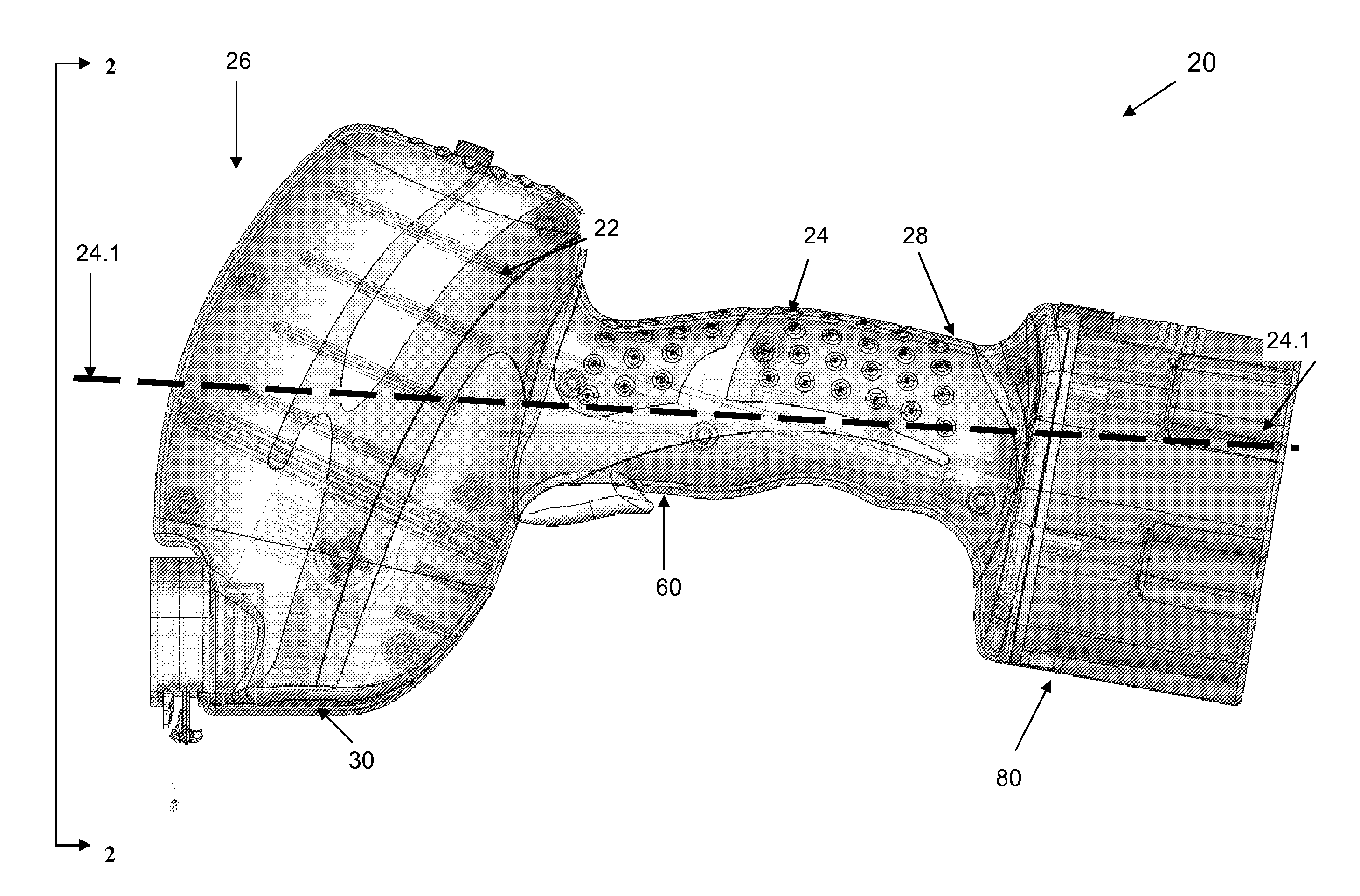
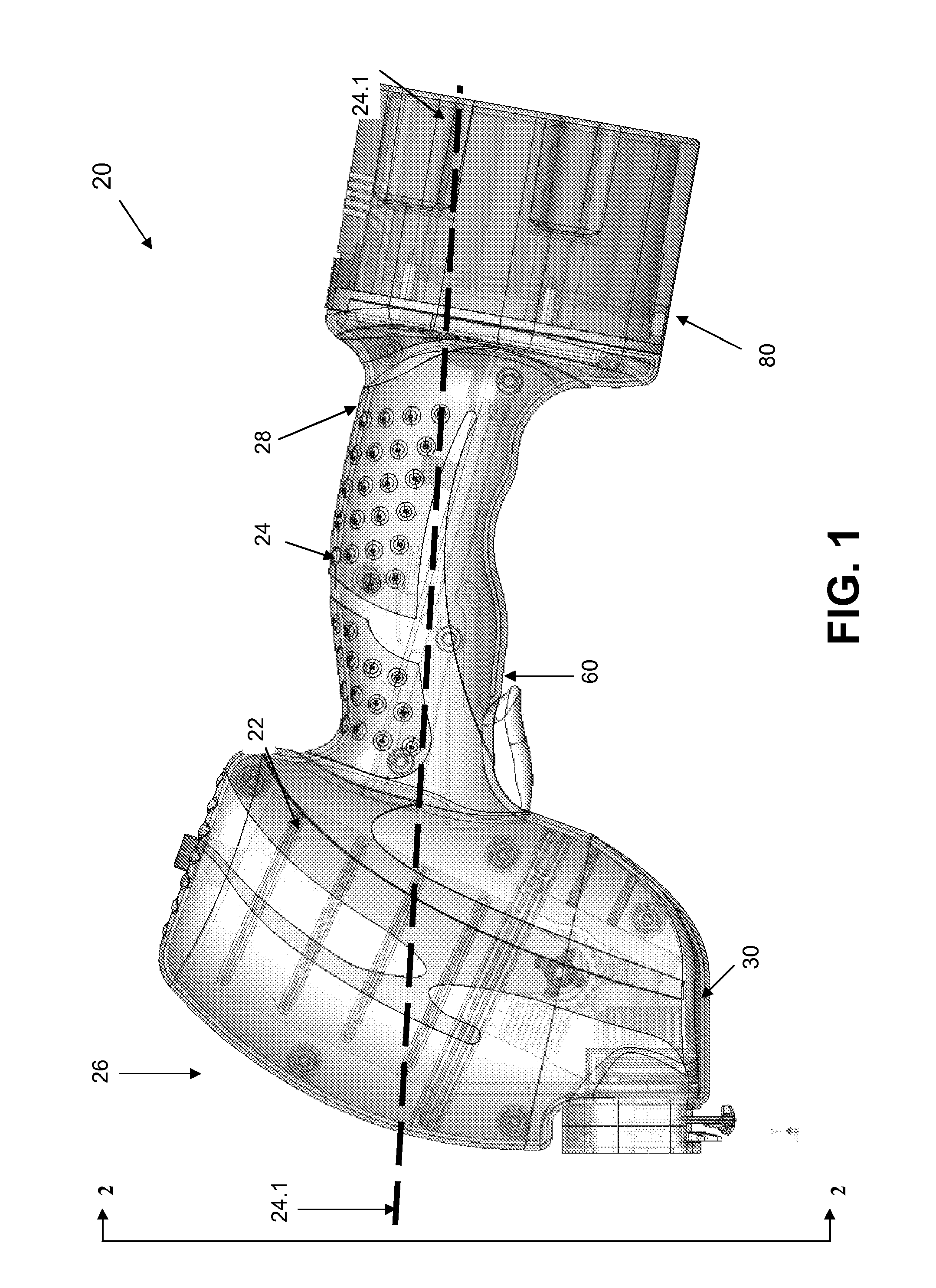
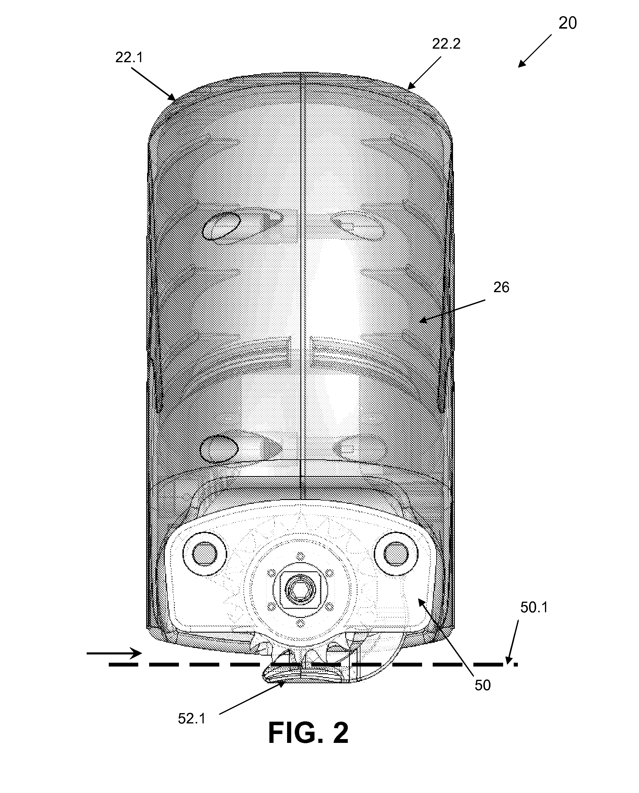
The present invention relates to an apparatus and method for cutting a layer of material with high torque at low speeds. The apparatus includes an electric motor, a wheel with shearing sectors, and a foot with a shearing surface. The method involves engaging the material with the shearing sectors and rotating the wheel at a high speed with low torque. The apparatus can be portable and includes a handle for easy operation. The technical effects of the invention include improved cutting performance and efficiency, as well as improved portability and ease of use.

Problems solved by technology

The hard outer cast shells typically are removed by using powered oscillating saws, which can be noisy and may create substantial fine debris.
However, oscillating saws can still cause burns or abrasions, and in many cases cause fear in many patients, especially small children.

Method used


Image

  • Cast removal system
  • Cast removal system
  • Cast removal system

Examples


Embodiment Construction

[0152]For the purposes of promoting an understanding of the principles of the invention, reference will now be made to the embodiments illustrated in the drawings and specific language will be used to describe the same. It will nevertheless be understood that no limitation of the scope of the invention is thereby intended, such alterations and further modifications in the illustrated device, and such further applications of the principles of the invention as illustrated therein being contemplated as would normally occur to one skilled in the art to which the invention relates. At least one embodiment of the present invention will be described and shown, and this application may show and / or describe other embodiments of the present invention. It is understood that any reference to “the invention” is a reference to an embodiment of the invention, with no single embodiment including an apparatus, process, or composition that must be included in all embodiments, unless otherwise stated....


PUM

PropertyMeasurementUnit
linear velocityaaaaaaaaaa
diameteraaaaaaaaaa
diameteraaaaaaaaaa

Abstract

Apparatus and methods for cutting a material, especially with low material speed and high cutting torque. In some embodiments, the apparatus is a hand-held device for quietly cutting through an orthopedic cast with little or no generation of debris. In yet other embodiments, there is a method for automatically advancing material past a shearing surface, such that the shearing action occurs at about the same velocity as the advancement. In yet other embodiments, there is a device for cutting material between a foot and a sharp edge, with the bottom of the foot being under the sharp edge to protect the skin of the patient.

Description

CROSS REFERENCE TO RELATED APPLICATIONS[0001]This application is a national stage application of PCT Patent Application No. PCT / US08 / 83453, filed Nov. 13, 2008, which claims the benefit of priority to U.S. Provisional Patent Applications Ser. No. 61 / 002,842, filed Nov. 13, 2007 entitled CAST REMOVAL SYSTEM I; Ser. No. 61 / 010,551, filed Jan. 9, 2008, entitled CAST REMOVAL SYSTEM II; Ser. No. 61 / 072,996, filed Apr. 4, 2008, entitled CAST REMOVAL SYSTEM III; and Ser. No. 61 / 104,061, filed Oct. 9, 2008, entitled CAST REMOVAL SYSTEM IV, all of which are incorporated herein by reference.FIELD OF THE INVENTION[0002]The present invention pertains to methods and apparatus for cutting through a material, and in particular to methods and apparatus for cutting through an orthopedic cast.BACKGROUND[0003]Casts used to set broken bones or other injuries to limbs generally consist of a hard outer shell, a sleeve, and an internal fabric or wrapping. The outer shell is typically made of layers of fib...

Claims


Application Information

Patent Timeline
Patent Type & Authority Patents(United States)
IPC IPC(8): A61F15/02B23D61/12B26B25/00B23D61/18B23D61/02B26D7/22
CPCA61F15/02B23D61/02B23D61/12B23D61/18B26B25/00Y10T83/04
Inventor ZWIRKOSKI, PAUL A.ADAMS, JOSEPH T.DEETER, NICK A.BARNETT, GARY D.VON SEGGERN, BOBJONES, MICHAEL C.
Owner ORTHOPEDIATRICS CORP
Learn More