
Ceiling transport vehicle

a transport vehicle and floor technology, applied in the direction of elevated railways, transportation and packaging, conveyors, etc., can solve the problems of high possibility and inability to precisely transfer articles to or from the transfer target location of articles, so as to reduce the number of actuators and simplify the configuration of switching means

Active Publication Date: 2015-10-27
DAIFUKU CO LTD
View PDF21 Cites 14 Cited by
  • Summary
  • Abstract
  • Description
  • Claims
  • Application Information

AI Technical Summary

Benefits of technology

The present invention provides a ceiling transport vehicle for transferring articles precisely and smoothly along a set travel path. The vehicle includes a guide rail and a pair of contacting members that can switch between a holding state to position and hold the vehicle in a specific location and a holding release state to allow the vehicle to travel smoothly along the set travel path. The guide rail includes a pair of rail portions spaced apart in the lateral width direction and a pair of guiding bodies provided between the rail portions to keep the vehicle stable and prevent tilting. The vehicle also includes a single actuator that can move the contacting members towards or away from each other, reducing the number of actuators required and simplifying the switching mechanism. Such a vehicle can transfer articles precisely and allows for smooth operation and positioning.

Problems solved by technology

And when the stop position of the travel portion is displaced in the lateral width direction with respect to the article transfer position, there is a high possibility that the article can not be transferred precisely to or from the article transfer target location.

Method used


Image

  • Ceiling transport vehicle
  • Ceiling transport vehicle
  • Ceiling transport vehicle

Examples


Embodiment Construction

[0032]An embodiment in which a ceiling transport vehicle of the present invention is provided to an article processing facility is described next with reference to the drawings.

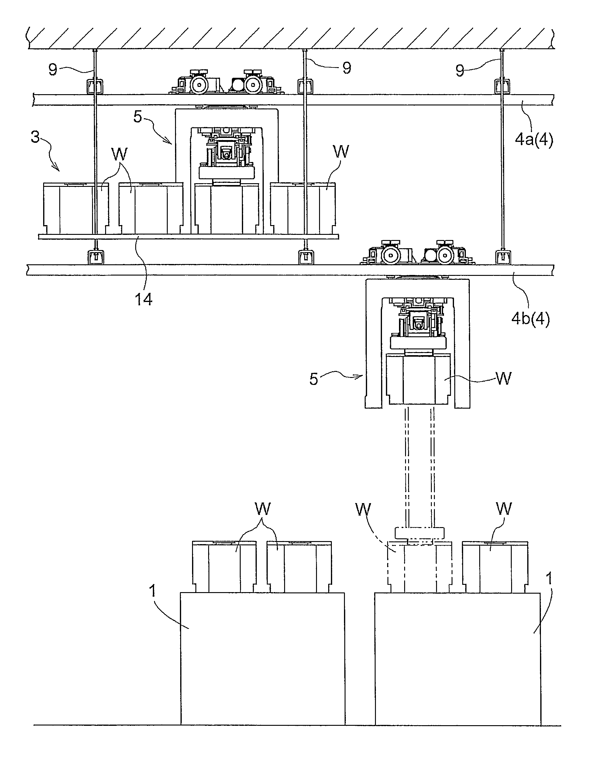
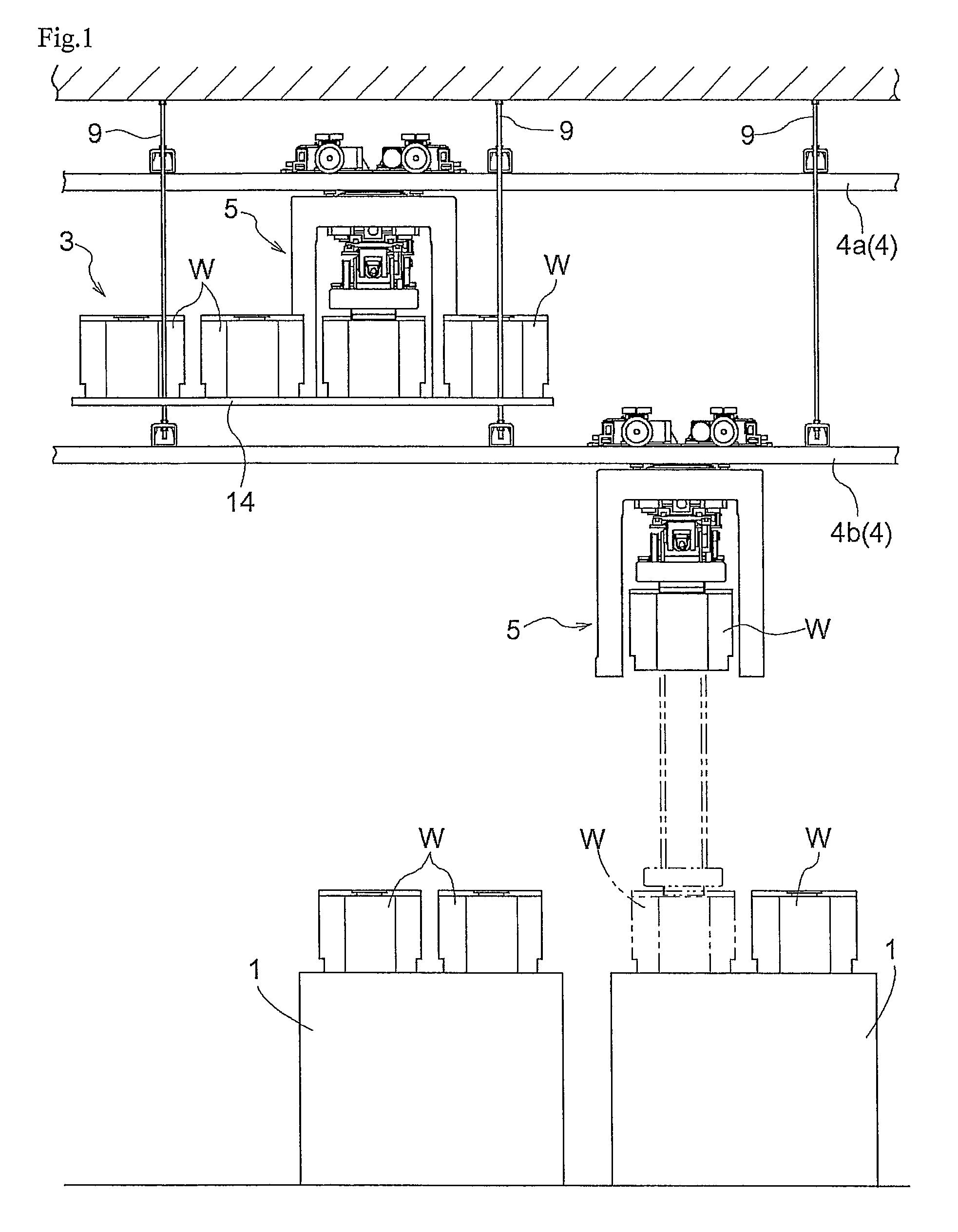
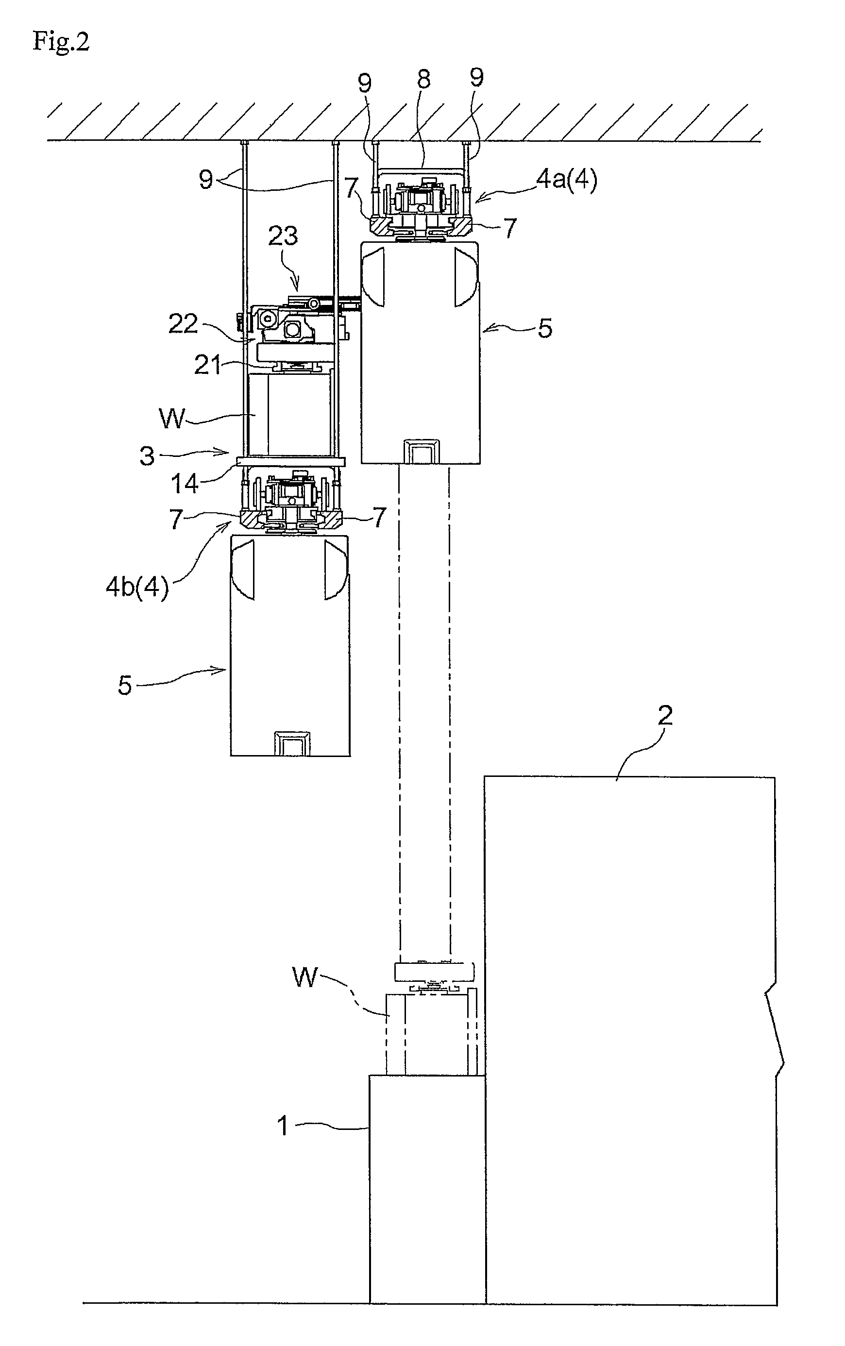
[0033]As shown in FIGS. 1-3, the article processing facility includes a plurality of processing devices 2 (see FIG. 2) each having a station 1, a storage shelf 3 which is suspended and supported by the ceiling and which can store a plurality of articles W, and ceiling transport vehicles 5 which travel along guide rails 4 installed on the ceiling side along a set travel path set up in advance such that the path extends by way of or adjacent to a plurality of processing devices 2 and the storage shelf 3. In addition, an article W is a container for storing semiconductor substrates, and the processing devices 2 perform predetermined processes to, for example, work-in-process parts which are semiconductor substrates that are being manufactured.

[0034]And each ceiling transport vehicle 5 is configured to transfer a...


PUM


Abstract

A ceiling transport vehicle in which articles may be transferred precisely while allowing its travel portion to travel smoothly along a set travel path is provided. The ceiling transport vehicle has a pair of guiding bodies which guide the travel portion along a set travel path by contacting each of right and left lateral sides of a guide rail with a pair of contacting members that are supported by the travel portion such that the contacting members can be moved away from each other and moved toward each other in a lateral width direction. The ceiling transport vehicle also has a switching portion for moving each of the pair of contacting members away from each other and toward each other to switch between a holding state and a holding release state.

Description

BACKGROUND OF THE INVENTION[0001]1. Field of the Invention[0002]The present invention relates to a ceiling transport vehicle comprising a travel portion that travels along a guide rail installed on a ceiling side along a set travel path, a main body portion that is suspended and supported by the travel portion and that supports an article such that the article can be moved vertically, and a pair of guiding bodies that contact right and left lateral sides of the guide rail to guide the travel portion along the set travel path.[0003]2. Description of Related Art[0004]Such ceiling transport vehicles are configured to guide its travel portion, which travels on a guide rail along a set travel path, with a pair of guiding bodies, and to vertically move an article with the travel portion stopped at an article transfer position, which is arranged at a location that corresponds to an article transfer target location in the travel path, so as to transfer the article to and from the article tr...

Claims


Application Information

Patent Timeline
Patent Type & Authority Patents(United States)
IPC IPC(8): B65G1/04B61B3/02H01L21/677
CPCB61B3/02H01L21/6773H01L21/67733B65G1/0464B65G2201/0297
Inventor WADA, YOSHINARI
Owner DAIFUKU CO LTD
Learn More