Spindle drive

a spindle and drive shaft technology, applied in the direction of toothed gearings, belts/chains/gearrings, gear details, etc., can solve the problems of difficult or impossible lubrication, and achieve the effect of reducing the overall siz

Active Publication Date: 2015-10-27
WITTENSTEIN SE
View PDF25 Cites 0 Cited by
  • Summary
  • Abstract
  • Description
  • Claims
  • Application Information

AI Technical Summary

Benefits of technology

[0006]Relubricating systems of embodiments have a stationary channel system and a rotating channel system which is connected to the stationary channel system, in order to guide lubricant to the lubricating channel outlet. The combination of a rotatable channel system with a stationary channel system achieves a situation where lubrication is also possible during the system. Here, the expression “rotatable” channel system is understood to mean that said channel system is rotated during operation or is received in a part which rotates during the operation, for example in a drive sleeve, or in a rotating spindle, if the embodiment comprises a rotatable spindle. A further possibility is that the rotatable channel system is arranged in the spindle nut if the latter is rotated in operation in the embodiment. Here, the expression “stationary” preferably means that the stationary channel system is arranged in a component or in components which is / are not rotated during operation. More preferably, the stationary channel system is arranged in components which are not rotated relative to a housing of the spindle drive or are not moved during operation. The combination of the channel systems makes flexible lubrication possible.
[0007]In typical embodiments, a transfer space is arranged between the stationary channel system and the rotatable channel system. The transfer space is usually configured to be at least partially concentric with respect to the longitudinal axis of the spindle. In embodiments, the transfer space is of annular configuration, it being possible for the annular shape to have interruptions in some embodiments. An annular transfer space affords the advantage of continuous loading of channels with lubricant. An at least partially concentric transfer space makes a simple arrangement possible in a housing or further components of the spindle drive. In general, a transfer space affords the advantage that a defined interface is provided between the rotatable channel system and the stationary channel system. The transfer space can also be called a rotary leadthrough, since a transition from a non-rotating system to a rotating system takes place at this location. In typical embodiments, the transfer space is sealed in the axial direction on one side or both sides by shaft sealing rings, sealing lips, sealing rings or other types of sealing systems. It is ensured in this way that a transfer of lubricant largely without losses is possible.
[0011]In embodiments, the spindle is connected fixedly to a hollow-shaft rotor so as to rotate with it, the rotating channel system also running through the hollow-shaft rotor. An arrangement of this type affords the advantage that lubrication can take place without dismantling of the hollow-shaft rotor. The hollow-shaft rotor is typically used to drive the spindle. Radial channels of the rotating channel system are usually arranged in the hollow-shaft rotor, but channels which additionally run in the axial direction can also be arranged in embodiments. In general, the expression “radial channel” is to be understood to mean channels of the type which have a radial directional component. The radial directional component can typically be more than 50%, that is to say the channels run at an angle of at most 45° relative to a radial direction of the spindle.

Problems solved by technology

In particular in the case of spindle drives which are installed in compact linear actuators, relubrication is difficult or impossible, without removal or partial dismantling of the linear actuator or the spindle drive taking place.

Method used


Image

  • Spindle drive
  • Spindle drive
  • Spindle drive

Examples


Embodiment Construction

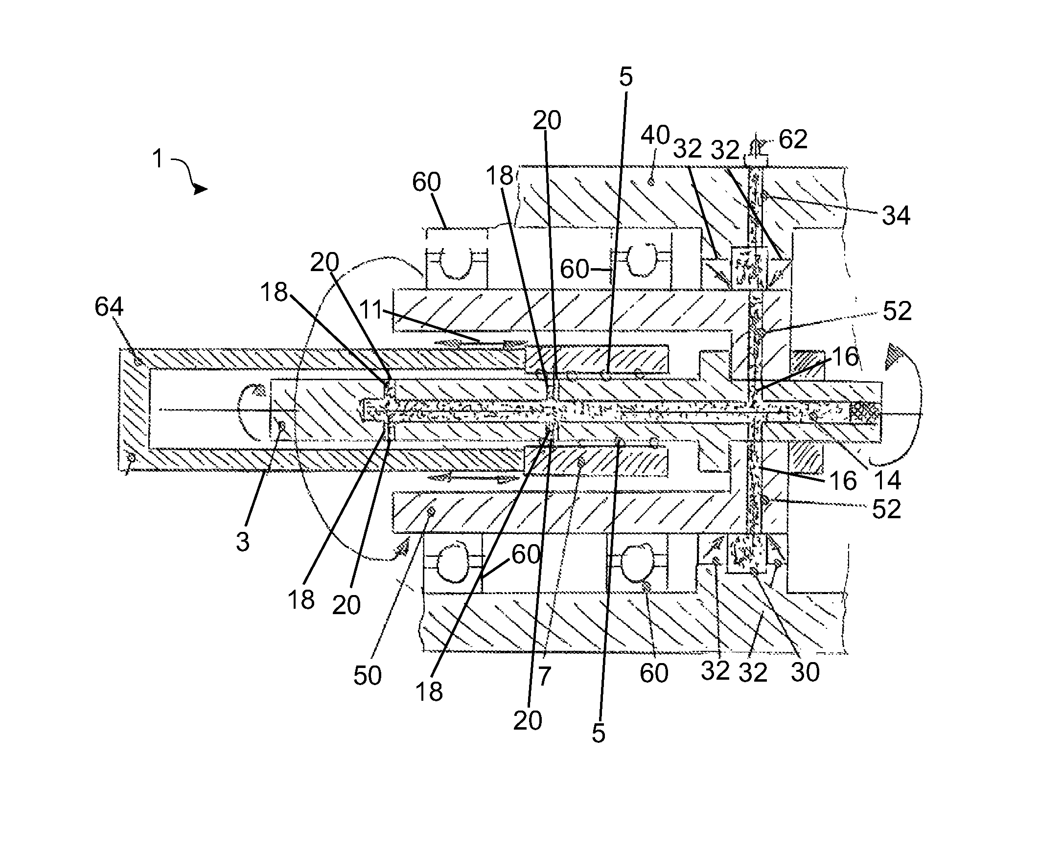
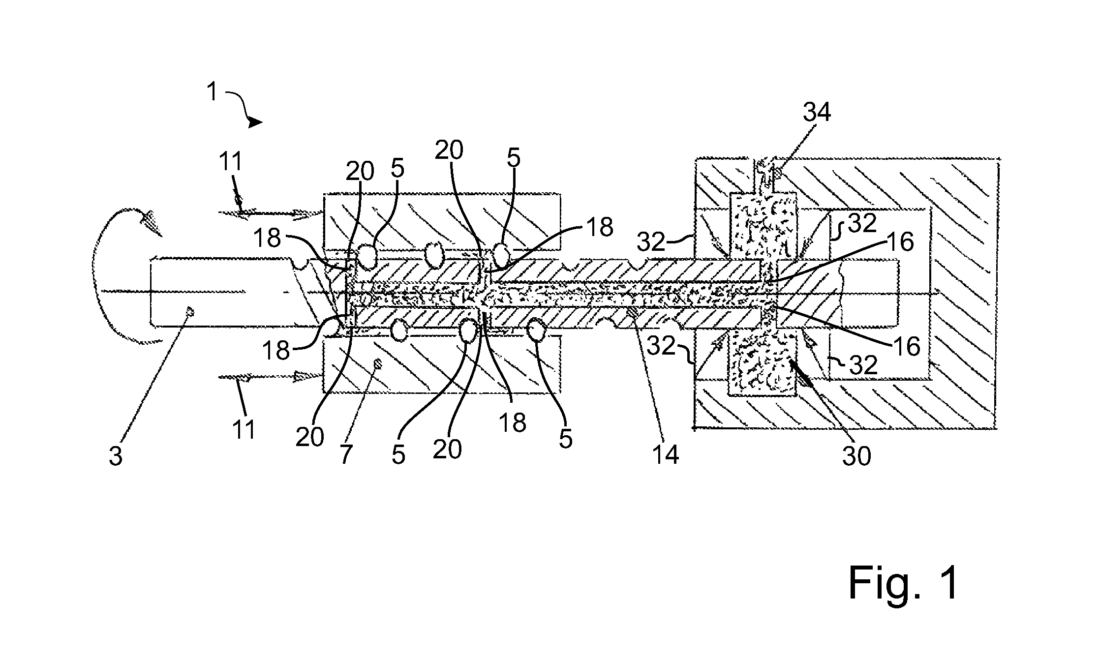
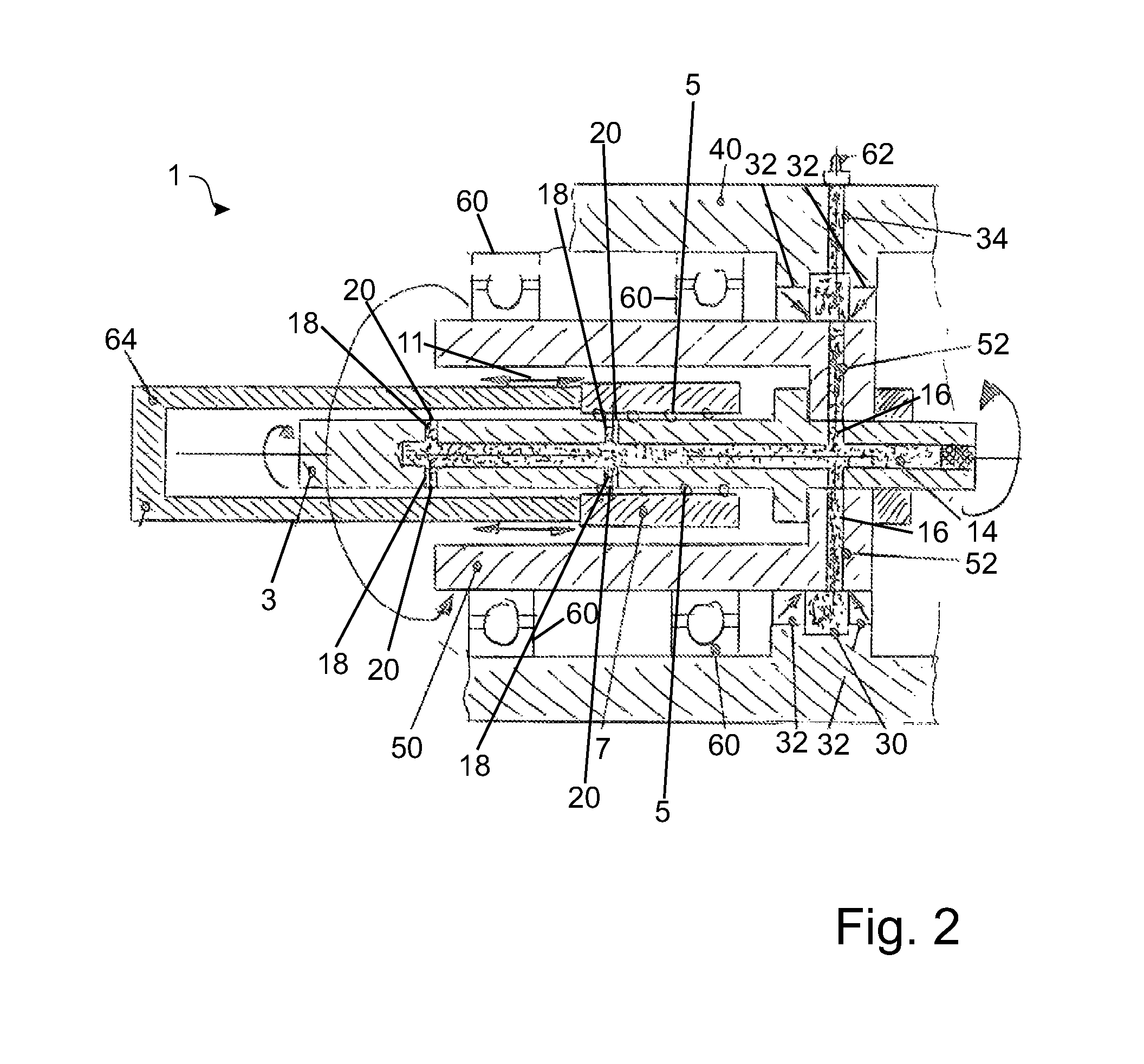
[0021]FIG. 1 shows one embodiment of a spindle drive 1. The spindle drive 1 has a spindle 3 which interacts via rolling bodies 5 with a spindle nut 7. In the embodiment of FIG. 1, the spindle 3 is mounted rotatably, it being provided during operation to drive the spindle 3, in order to achieve an axial movement along the double arrows 11 on the spindle nut 7.

[0022]A rotatable channel system which has a longitudinal channel 14 for lubricant along the center axis of the spindle 3 is provided within the spindle 3. Lubricant is indicated within the lubricant channels in a dotted manner in each case in all drawings, which lubricant is present at least temporarily in the channels during operation. However, the lubricant is generally not a constituent part of the invention.

[0023]The longitudinal channel 14 is supplied with lubricant by first radial lubricating channels 16. The lubricant is guided via the longitudinal channel 14 to second radial lubricating channels 18 which open into lubri...


PUM


Abstract

A spindle drive (1), in particular for a linear actuator, having a spindle (3), a spindle nut (7) which interacts with the spindle (3), and a lubricating channel outlet (20) which opens into an intermediate space between the spindle (3) and the spindle nut (7) for lubricating the spindle (3) and the spindle nut (7), the spindle drive (1) comprising, moreover, a stationary channel system and a rotatable channel system which is connected to the stationary channel system for feeding lubricant to the lubricating channel outlet (20).

Description

BACKGROUND OF THE INVENTION[0001]The invention relates to a spindle drive for a linear actuator.[0002]The prior art discloses spindle drives which are used to convert rotating movements into linear movements or vice versa. In particular in the case of spindle drives which are installed in compact linear actuators, relubrication is difficult or impossible, without removal or partial dismantling of the linear actuator or the spindle drive taking place. Maintenance during running operation is frequently completely ruled out.[0003]The invention is based on the object of improving spindle drives which are known from the prior art; in particular, spindle drives which are installed in linear actuators are to be improved, with the result that simple relubrication is made possible. In particular, relubrication during running operation is to be possible.SUMMARY OF THE INVENTION[0004]The object is achieved by way of a spindle drive comprising a spindle nut which interacts with the spindle, and...

Claims


Application Information

Patent Timeline
Patent Type & Authority Patents(United States)
IPC IPC(8): F16H3/06F16H29/20F16H27/02F16H57/04F16H25/12F16H29/02F16H25/22
CPCF16H25/12F16H57/043F16H57/0497F16H25/2204Y10T74/18744
Inventor SCHWARZBACH, MICHAEL
Owner WITTENSTEIN SE
Why Eureka
Try Eureka