Motion recognition method
- Summary
- Abstract
- Description
- Claims
- Application Information
AI Technical Summary
Benefits of technology
Problems solved by technology
Method used
Image
Examples
first embodiment
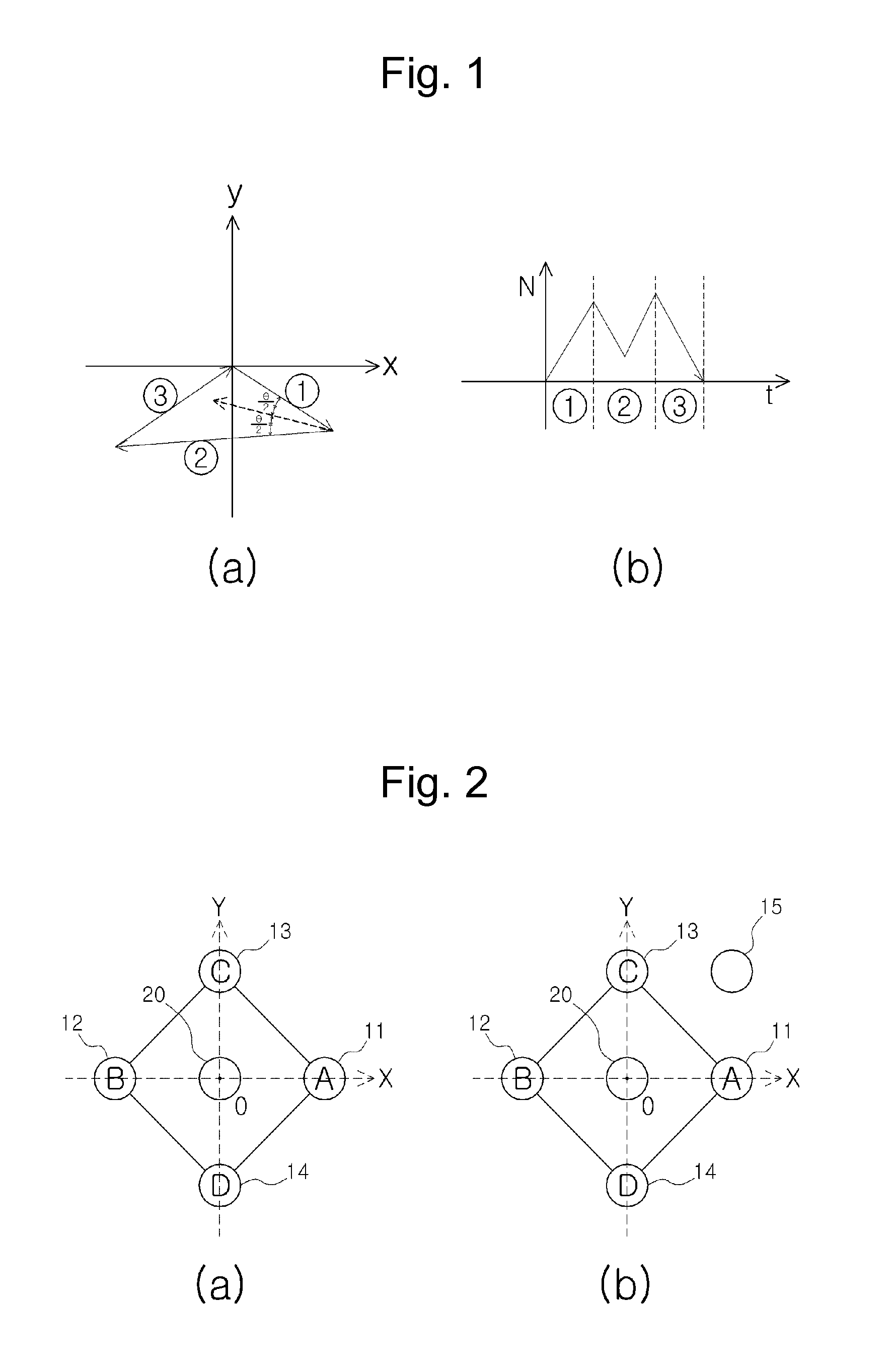
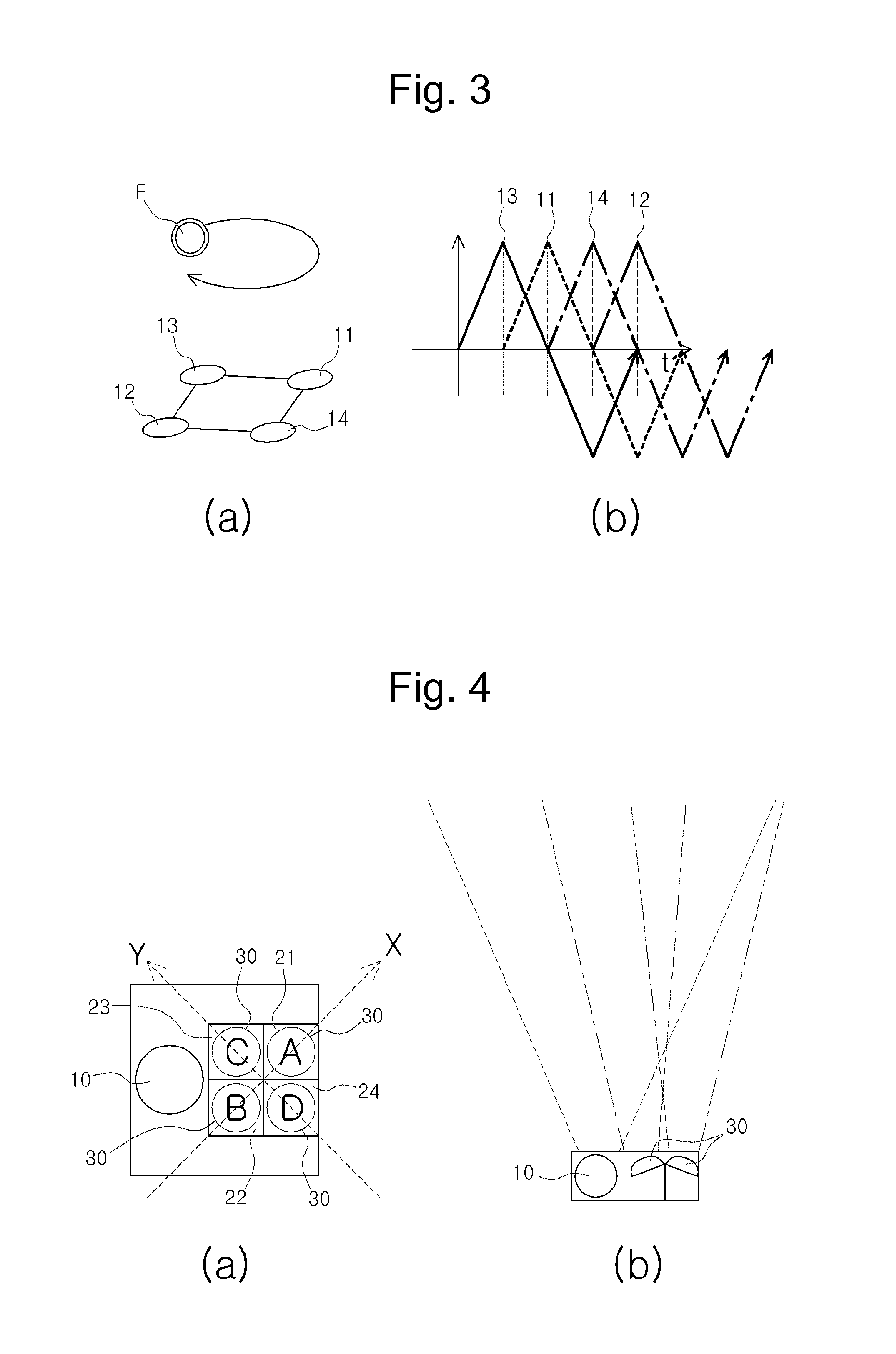
[0058]FIG. 2A is a view schematically showing a structure of a motion switch according to a first embodiment of the present invention. FIG. 2B shows a motion switch further including an interpolation element in FIG. 2A. FIG. 3 is a view showing a recognition pattern of a special motion of a reflective body.
[0059]The motion switch for realizing the motion recognition method according to the present invention includes a light emitting element 10, a light receiving element 20, and a data processing unit (not shown).
[0060]The light receiving element 10 includes first and second light emitting elements 11 and 12 disposed to face each other while taking the light receiving element 20 as the center thereof, and third and fourth light emitting elements 13 and 14 disposed to face each other while taking the light receiving element 20 as the center thereof, and the first to fourth light emitting elements 11, 12, 13, and 14 are disposed to be spaced apart from each other by an interval of 90° ...
second embodiment
[0084]The second embodiment is different from the first embodiment in an aspect of disposition structures of the light emitting device and the light receiving structure.
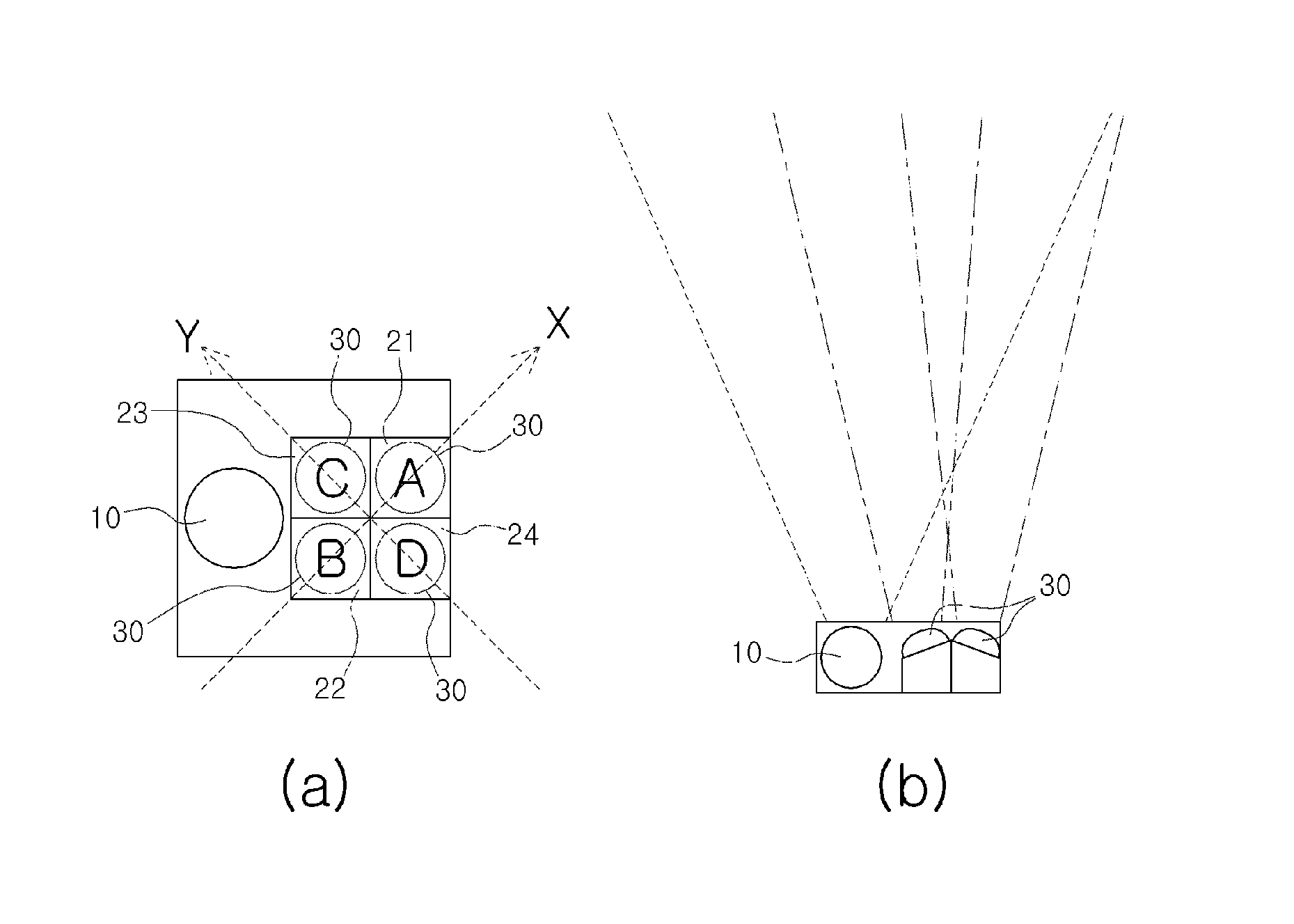
[0085]FIG. 4A is a view schematically showing a planar structure of a motion switch according to a second embodiment of the present invention. FIG. 4B is a view schematically showing a side structure of the motion switch according to the second embodiment of the present invention.
[0086]The motion switch for realizing the motion recognition method according to the second embodiment of the present invention includes a light emitting element 10, a light receiving element 20, and a data processing unit (not shown).
[0087]The light emitting element 10 projects light at a predetermined interval.
[0088]The light receiving elements 20 are disposed to be spaced apart from each other at an interval of 90° while taking the origin acting as the center of the entire light reception range as the center thereof, and the light emittin...
third embodiment
[0133]FIG. 13 is a view schematically showing a planar structure of a motion switch according to a third embodiment of the present invention.
[0134]The motion switch for realizing the motion recognition method according to the present invention includes a light emitting element 10, a light receiving element 20, and a data processing unit.
[0135]The light receiving element 10 includes first and second light emitting elements 11 and 12 disposed to face each other while taking the light receiving element 20 as the center thereof, and third and fourth light emitting elements 13 and 14 disposed to face each other while taking the light receiving element 20 as the center thereof, and the first to fourth light emitting elements 11, 12, 13, and 14 are disposed to be spaced apart from each other by an interval of 90° while taking the light receiving element 20 as the center thereof to sequentially project light at a predetermined interval.
[0136]Accordingly, if a reflective body such as a hand ...
PUM
 Abstract
Description
Claims
Application Information
 - R&D
- Intellectual Property
- Life Sciences
- Materials
- Tech Scout
- Unparalleled Data Quality
- Higher Quality Content
- 60% Fewer Hallucinations
Browse by: Latest US Patents, China's latest patents, Technical Efficacy Thesaurus, Application Domain, Technology Topic, Popular Technical Reports.
© 2025 PatSnap. All rights reserved.Legal|Privacy policy|Modern Slavery Act Transparency Statement|Sitemap|About US| Contact US: help@patsnap.com


