
Active functional limiting of a microcontroller

a microcontroller and functional limitation technology, applied in the field of microcontrollers, can solve the problems of no longer controlling the internal combustion engine, too imprecise for bus communication, etc., and achieve the effect of reducing the precision of the clock generation in the case of the second clock and being less precis

Active Publication Date: 2015-11-03
ROBERT BOSCH GMBH
View PDF10 Cites 0 Cited by
  • Summary
  • Abstract
  • Description
  • Claims
  • Application Information

AI Technical Summary

Benefits of technology

[0014]The microcontroller according to the present invention and the method according to the present invention thus permit a read or write access to internal data in the microcontroller from the outside, even after the provision and use of this microcontroller, for example in a motor vehicle. With these data, for example field returns can be analyzed. The changeover of the clock caused by an access therefore enables a determination of a previous access to the microcontroller. In this way, a manipulation of the microcontroller can be detected, and / or a use of the microcontroller after an access to the data can be made impossible. In particular, warranty claims that may be raised can be rejected, and / or the safety of a vehicle can be increased.
[0017]The second clock is preferably less precise than the first. Preferably, the precision of the clock generation in the case of the second clock is reduced far enough that, given a use of the microcontroller in a control device, communication is no longer possible between the control device and another control unit of the internal combustion engine. For example, the second clock can be selected such that, in contrast to the first clock, it is too imprecise to permit the use of a suitable bus system (such as a FlexRay field bus system or a CAN bus). In this way, the use of the microcontroller after an access to the internal data thereof in an internal combustion engine can be prevented. The second clock can for example be generated by an uncalibrated internal RC oscillator, or by a pseudorandom clock generator.

Problems solved by technology

The second clock is in particular selected such that while it does continue to permit a data communication between the microcontroller and an external access device via the analysis access, it is however too imprecise for a bus communication.
The control device can then still be read out and / or written to, but can no longer control the internal combustion engine.

Method used


Image

  • Active functional limiting of a microcontroller
  • Active functional limiting of a microcontroller
  • Active functional limiting of a microcontroller

Examples


Embodiment Construction

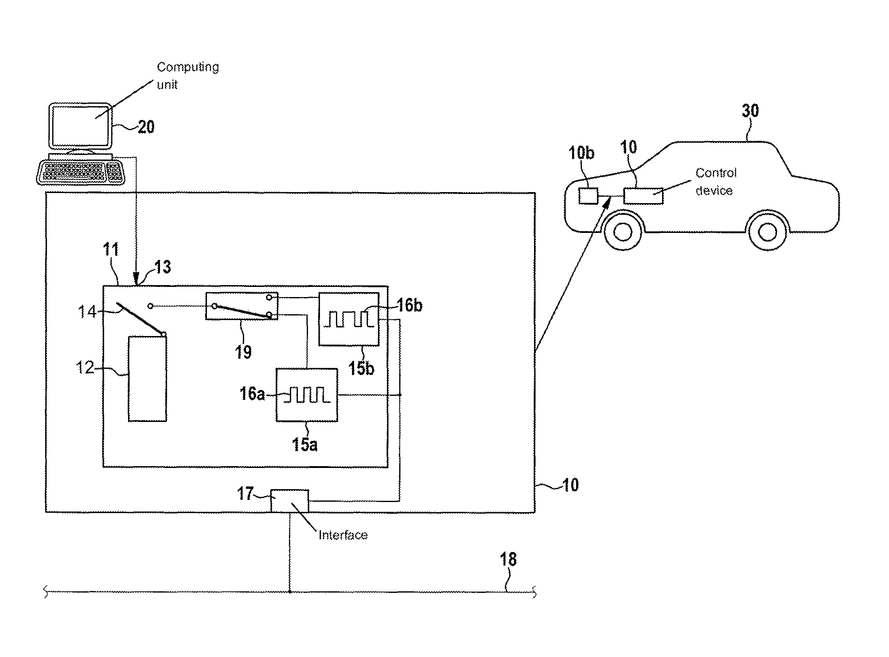
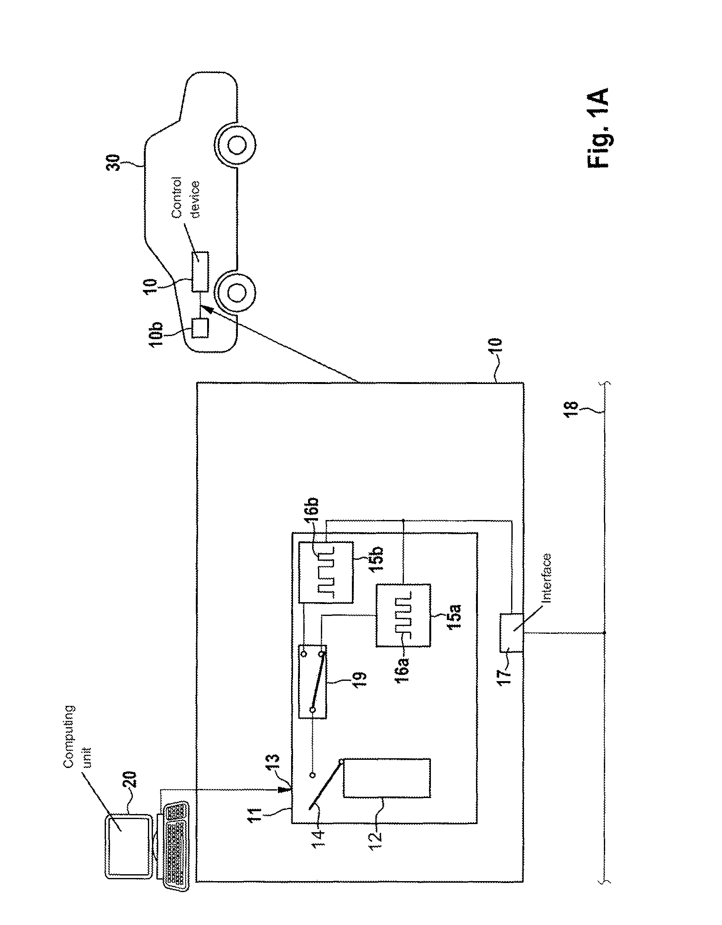
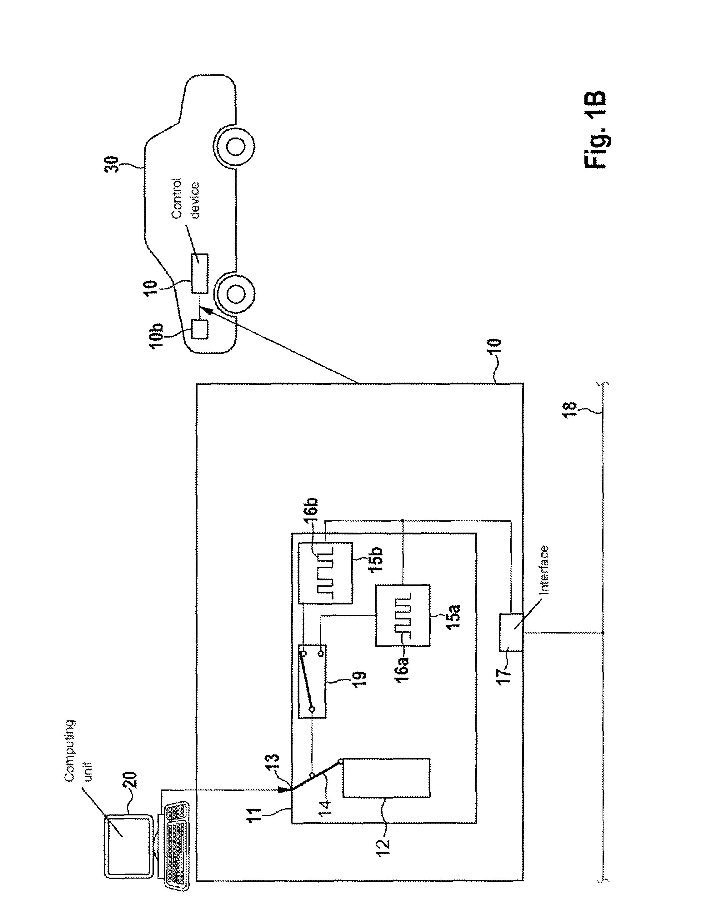
[0023]FIGS. 1A and 1B show a microcontroller 11 that is used in a control device 10 for a motor vehicle 30. The microcontroller has an internal memory device 12 and an analysis access 13 (which can at the same time be a debug access). The possibility of opening and closing the analysis access is shown symbolically in FIGS. 1A and 1B by switch 14. In FIG. 1A the access is closed, and in FIG. 1B it is open. When analysis access 13 is open, an external computing unit 20 can access internal data in memory 12.

[0024]Depicted microcontroller 11 has, as clock generating means, units 15a and 15b for clock generation. Unit 15a generates a first clock 16a , and unit 15b generates a second clock 16b. Unit 15a can for example be an internal phase-locked loop in connection with an external quartz crystal, and unit 15b can be for example an uncalibrated internal RC oscillator or a pseudorandom clock generator.

[0025]Both units are connected to an interface 17 of the control device. Via interface 17...


PUM


Abstract

A microcontroller for use in a control device for an internal combustion engine includes: an analysis access via which internal data in the microcontroller can be accessed from outside the microcontroller; a clock generator which generates clock timing for data communication of the microcontroller with other units. The microcontroller is configured to change over from a first clock to a second clock when there is an access to the microcontroller via the analysis access.

Description

BACKGROUND OF THE INVENTION[0001]1. Field of the Invention[0002]The present invention relates to a microcontroller for a control device for an internal combustion engine, to a control device for an internal combustion engine, to a method for the functional controlling of a microcontroller, and to a computer program for the functional limiting of a microcontroller.[0003]2. Description of the Related Art[0004]The task of an engine control device of an internal combustion engine is to calculate output quantities for actuating elements (such as injection nozzles or an ignition system) from a multiplicity of input signals (such as rotational speed, temperature, or pressure). For this purpose, a control device has a microcontroller having its own storage device (so-called on-chip storage), in which the data, characteristic maps, and / or programs required for the calculation—also generally referred to below as internal data—are stored.[0005]During the manufacturing of the control device, pa...

Claims


Application Information

Patent Timeline
Patent Type & Authority Patents(United States)
IPC IPC(8): F02D41/26G06F21/74G06F21/00G06F13/12G06F1/06F02D41/28
CPCG06F1/06F02D41/26F02D41/28G06F13/12G06F21/00G06F21/74F02D2041/286
Inventor AUE, AXELSCHREIBER, MATTHIAS
Owner ROBERT BOSCH GMBH
Learn More