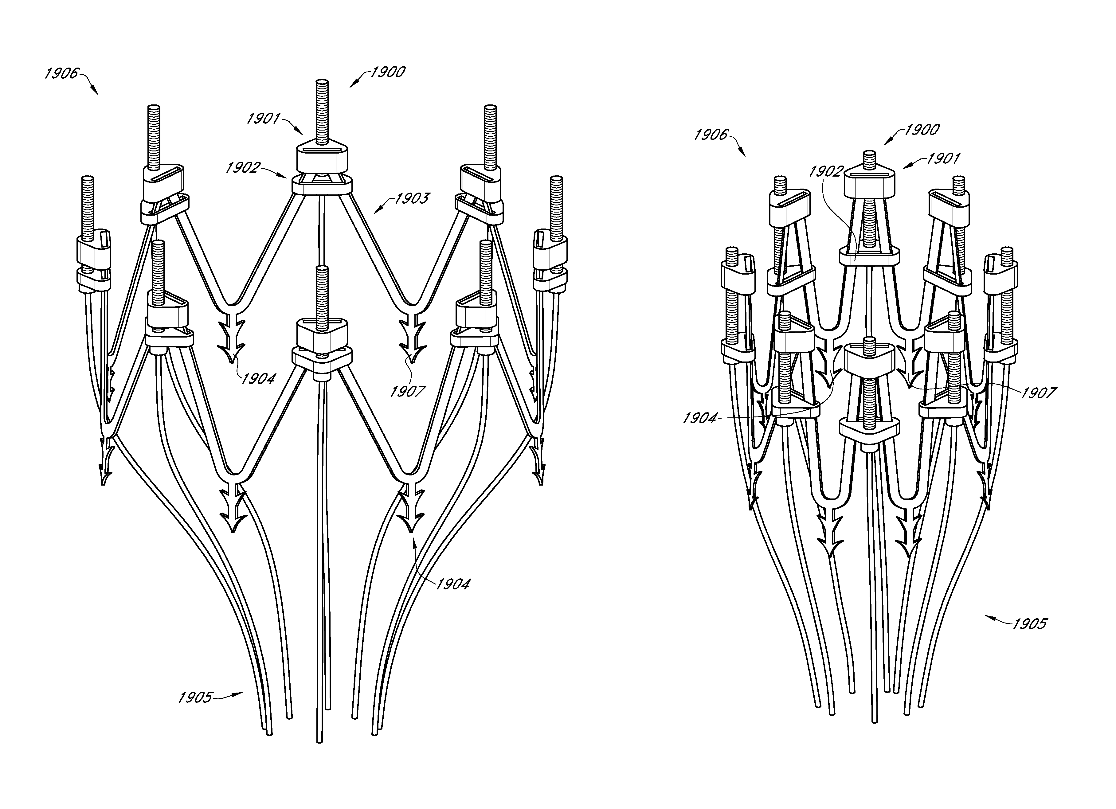
Adjustable endolumenal mitral valve ring

a technology of endolumenal mitral valve and adjustable endolumenal valve, which is applied in the field of heart disease treatment, can solve the problems of excessive dilatation of mitral annulus (e.g. mitral valve annulus) and chambers of the heart to expand and/or weaken, and achieve the effect of reducing or eliminating mitral regurgitation

Active Publication Date: 2015-11-10
BOSTON SCI SCIMED INC
View PDF210 Cites 286 Cited by
  • Summary
  • Abstract
  • Description
  • Claims
  • Application Information

AI Technical Summary

Benefits of technology

[0011]The implant size and / or shape may then be changed by a number of adjustment mechanisms, including mechanisms that use nuts, clips, and / or cables. Some mechanisms serve as restraints to adjustably change the distance between two or more anchors on the implant, such as through a working range, and ultimately affect the size and / or shape of a valve annulus, such as the mitral valve annulus. The adjustment of these mechanisms may be performed by using rotational drivers and / or actuators at the proximal end of the handle of the delivery catheter. The rotational drivers and / or actuators may be used to compress or expand the implant at the operator's discretion to adjust the final size and / or shape of the implant (and hence, the mitral valve) as desired. The delivery system may be disconnected and removed once the implant has been delivered and adjusted as desired, and / or once mitral regurgitation has been reduced or eliminated. The implant may be left as a permanent implant.

Problems solved by technology

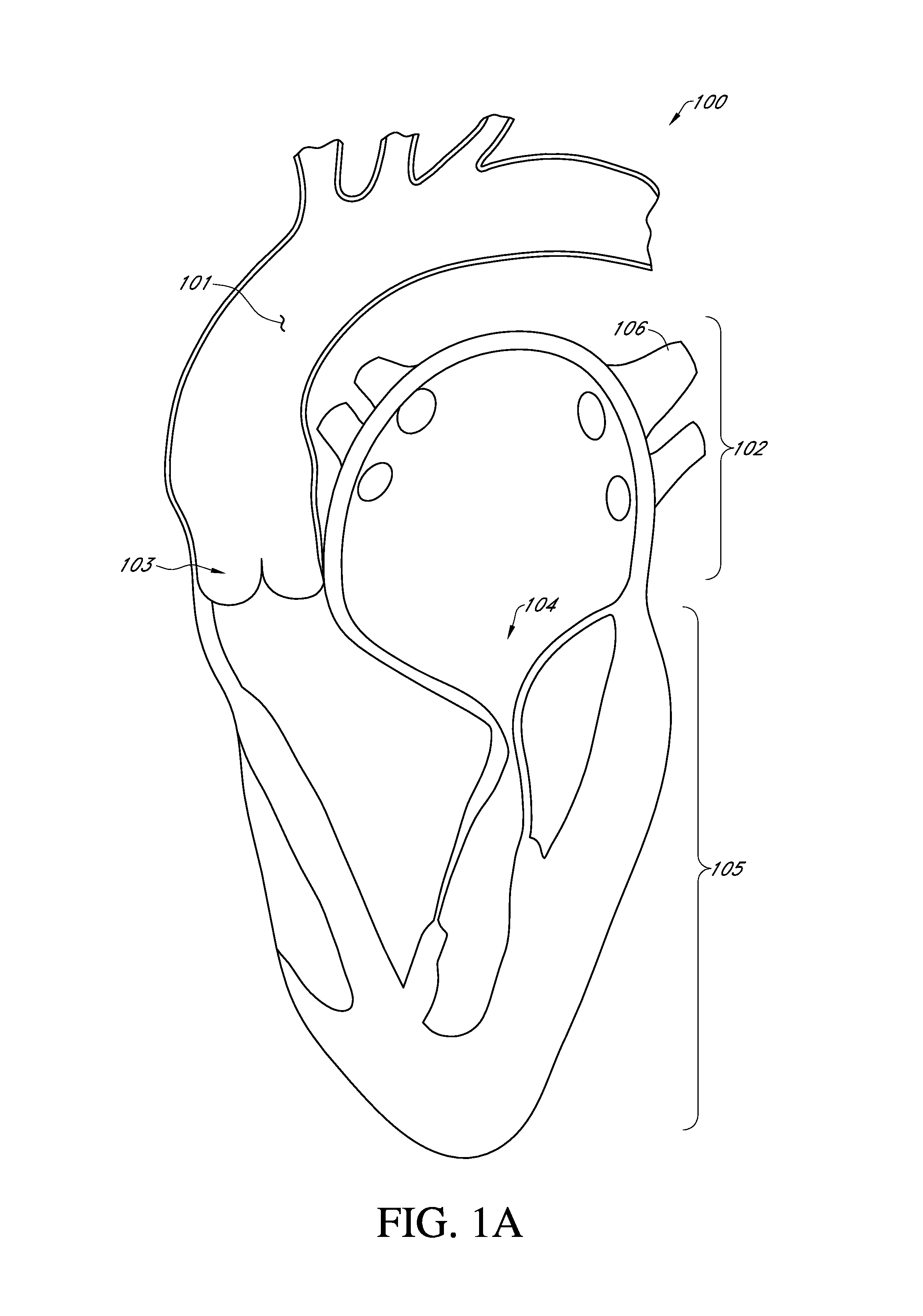
Heart disease can cause the chambers of the heart to expand and / or weaken.
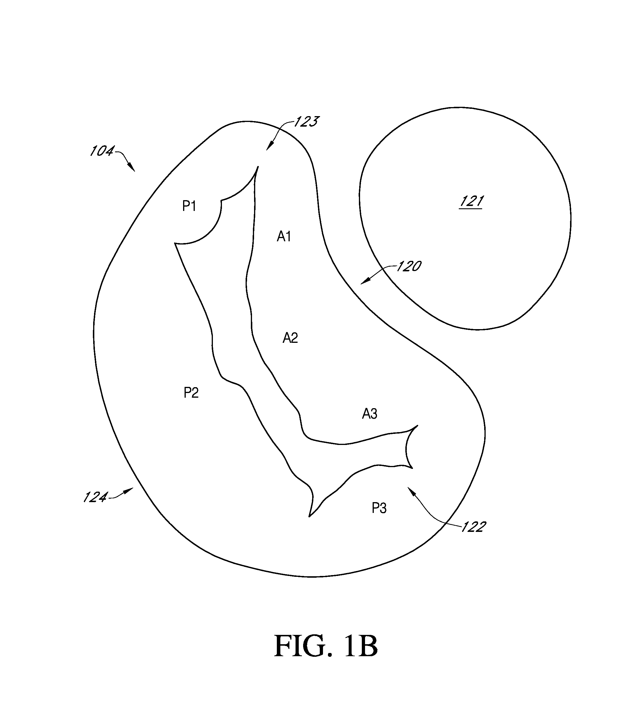
When the mitral valve is incompetent due to heart disease, the mitral annulus (e.g., the annulus of the mitral valve) dilates excessively.
Open heart-surgery is highly invasive and has many associated risks, including risks of infection, heart attack and / or stroke, memory loss, blood clots, blood loss, injury to the surrounding anatomy, and / or many other pains and / or discomforts.

Method used


Image

  • Adjustable endolumenal mitral valve ring
  • Adjustable endolumenal mitral valve ring
  • Adjustable endolumenal mitral valve ring

Examples


Embodiment Construction

[0049]This disclosure encompasses all changes, substitutions, variations, alterations, and modifications to the example embodiments herein that a person having ordinary skill in the art would comprehend. Similarly, where appropriate, the appended claims encompass all changes, substitutions, variations, alterations, and modifications to the example embodiments herein that a person having ordinary skill in the art would comprehend. Moreover, reference in the appended claims to an apparatus or system or a component of an apparatus or system being adapted to, arranged to, capable of, configured to, enabled to, operable to, or operative to perform a particular function encompasses that apparatus, system, component, whether or not it or that particular function is activated, turned on, or unlocked, as long as that apparatus, system, or component is so adapted, arranged, capable, configured, enabled, operable, or operative. For example, various embodiments may perform all, some, or none of...


PUM


Abstract

Excessive dilation of the annulus of a mitral valve may lead to regurgitation of blood during ventricular contraction. This regurgitation may lead to a reduction in cardiac output. Disclosed are systems and methods relating to an implant configured for reshaping a mitral valve. The implant comprises a plurality of struts with anchors for tissue engagement. The implant is compressible to a first, reduced diameter for transluminal navigation and delivery to the left atrium of a heart. The implant may then expand to a second, enlarged diameter to embed its anchors to the tissue surrounding and/or including the mitral valve. The implant may then contract to a third, intermediate diameter, pulling the tissue radially inwardly, thereby reducing the mitral valve and lessening any of the associated symptoms including mitral regurgitation.

Description

CROSS-REFERENCE TO RELATED APPLICATIONS[0001]This application claims the priority benefit under 35 U.S.C. §119(e) of U.S. Provisional Application No. 62 / 025,967, filed Jul. 17, 2014, and U.S. Provisional Application No. 62 / 038,032, filed Aug. 15, 2014, the entireties of which are hereby incorporated by reference herein.BACKGROUND[0002]1. Field[0003]The present application relates generally to treating heart disease, and more specifically, to methods and systems for an adjustable endolumenal mitral valve ring.[0004]2. Description of Related Art[0005]Heart disease can cause the chambers of the heart to expand and / or weaken. With specific reference to the mitral valve of the heart, when the left ventricle dilates, papillary muscles become displaced. When the mitral valve is incompetent due to heart disease, the mitral annulus (e.g., the annulus of the mitral valve) dilates excessively. In this state of dilation, the valve leaflets of the mitral valve no longer effectively close, or coa...

Claims


Application Information

Patent Timeline
Patent Type & Authority Patents(United States)
IPC IPC(8): A61F2/24
CPCA61F2/2445A61F2/2466A61F2220/0016A61F2/2409A61F2/2418A61F2/93A61F2002/91591A61F2250/001A61F2250/0006A61F2230/0065A61F2230/0069A61F2210/0023A61B2017/0649A61F2220/0091A61F2220/0033A61F2002/9534A61M25/0147A61M25/0136A61M25/0152A61M25/0133A61M2025/0681A61M25/0662A61M2210/125A61F2/02A61F2/2412A61F2/2442A61F2/2463
Inventor LASHINSKI, RANDALLRUST, MATTHEWMACAULAY, PATRICKDANIELS, TERRY WAYNEKRISTOFFERSEN, KRIS
Owner BOSTON SCI SCIMED INC
Why Eureka
Try Eureka