Flexible linking device for an aircraft propulsion system

a technology of flexible linking and aircraft propulsion, which is applied in the direction of springs/dampers, power plant construction, rubber-like material springs, etc., can solve the problems of increasing the wear and tear of the fuselage structure, affecting the comfort of passengers, and in theory affecting the vibrations of the turbine engin

Active Publication Date: 2015-11-10
AIRBUS OPERATIONS (SAS)
View PDF11 Cites 10 Cited by
  • Summary
  • Abstract
  • Description
  • Claims
  • Application Information

AI Technical Summary

Benefits of technology

[0017]One object of the invention is thus a linking device having a certain flexibility, and enabling two elements to be connected by means of shafts.
[0034]The layers of elastomer material provide the cohesion of the entire device. Due to their capacity for elastic deformation, these layers of elastomer material allow relative movement of the shafts, and exert a return force urging each of the shafts towards a neutral position corresponding to a non-deformed state of these layers of elastomer material.
[0035]Due to the fact that the two shafts can move relative to one another, the linking device according to the invention allows moderate vibrations from one of the two shafts to be transmitted to the other shaft in an attenuated form. The linking device thus accomplishes a filtering of such vibrations.
[0048]at least one of the plates of the first and / or second type(s), hereinafter called a “more rigid plate”, has greater rigidity than other plates of the first and second types;
[0053]This characteristic notably allows improved control of the mechanical behavior of the linking device when it is subject to high-level forces, and in particular enables the dimensioning of the device to be facilitated for a given application.
[0073]This characteristic is not required for the definition of said paths, due to the fact that each connecting unit is guided by the third shaft, as explained above. Nevertheless, this characteristic enables the forces passing through the third shaft to be better controlled.

Problems solved by technology

This is particularly disadvantageous in the case of propulsion systems attached to the fuselage, as described above, since the vibrations are in that case transmitted directly to the structure of the airplane's fuselage.
These vibrations are thus likely to increase wear and tear of the structure of the fuselage, and to impair the passengers' comfort.
In these latter propulsion systems the vibrations caused by the turbine engines are in theory damped by the flexibility of the wing surface.
However, when the intensity of these vibrations is particularly high, notably in the event of a turbine engine operating incident, the vibrations of this turbine engine may also be transmitted to the structure of the airplane's fuselage.

Method used


Image

  • Flexible linking device for an aircraft propulsion system
  • Flexible linking device for an aircraft propulsion system
  • Flexible linking device for an aircraft propulsion system

Examples


Embodiment Construction

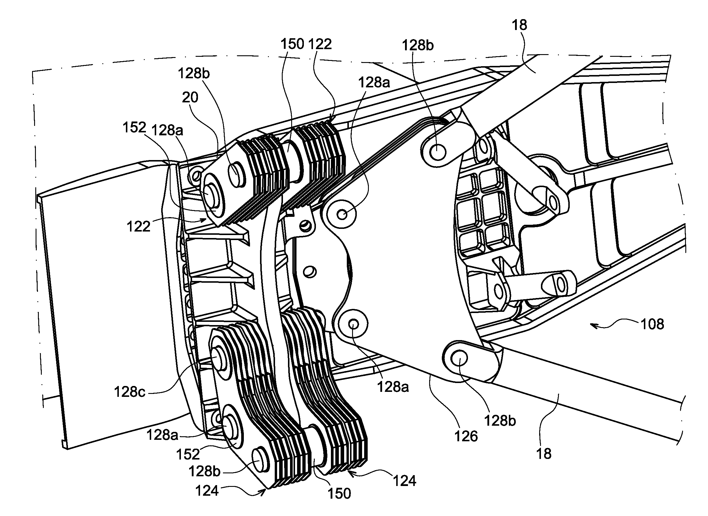
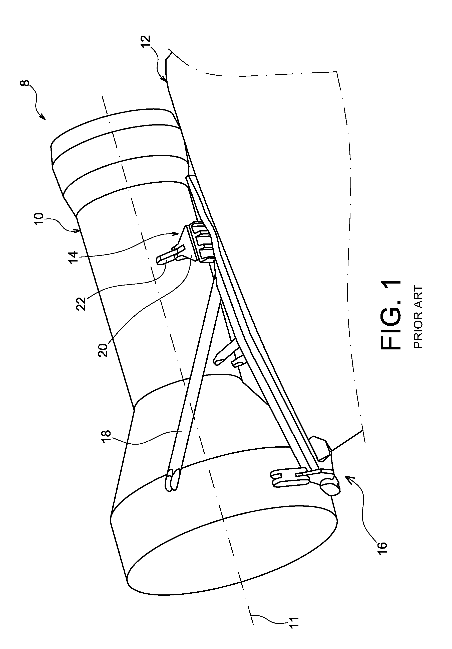
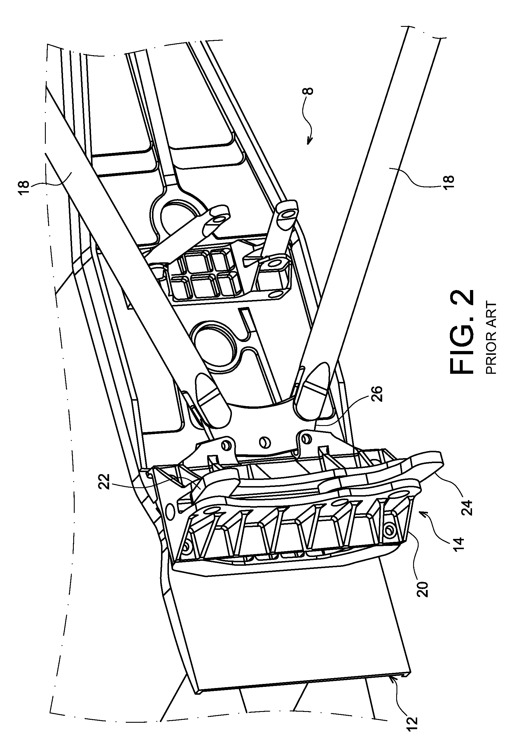
[0097]FIG. 3 illustrates a propulsion system 108 for an aircraft, which is similar to propulsion system 8 of FIGS. 1 and 2, but which includes linking devices which allow the vibrations of the turbine engine to be filtered. For reasons of clarity this turbine engine cannot be seen in FIG. 3.

[0098]Forward engine attachment 114 thus includes two connecting rods 122 and two three-point shackles 124, which have appropriate flexibility for such filtering of vibrations. The same applies to spreader beam 126, to which thrust force transfer connecting rods 18 are connected.

[0099]The two connecting rods 122 are similar and installed parallel with one another, i.e., they have the same axes, such that they provide an intrinsic safety function, also called a failsafe function, as will be shown more clearly in what follows. The same applies as regards the two three-point shackles 124.

[0100]Connecting rods 122, spreader beam 126, and shackles 124 are three linking devices according to the present...


PUM


Abstract

A linking device including two hinge pins and having flexibility allowing vibrations between these two shafts to be filtered. The device includes a stack of plates connected to one another by layers of elastomer material. Plates of a first type are coupled to one of the shafts in relation to the movements parallel to the plates, while the plates of a second type are coupled to the other shaft in relation to the movements parallel to the plates, so as to allow relative movement of the shafts parallel to the plates. This linking device may be used in particular as a connecting rod, spreader beam or three-point shackle used in connecting a turbine engine to a pylon in a propulsion system of an aircraft such as an airplane.

Description

CROSS-REFERENCES TO RELATED APPLICATIONS[0001]This application claims the benefit of the French patent application No. 1262950 filed on Dec. 28, 2012, the entire disclosures of which are incorporated herein by way of reference.BACKGROUND OF THE INVENTION[0002]The present invention relates to a linking device including at least two shafts intended for the reciprocal articulation of two elements, and allowing filtering of vibrations between the two shafts.[0003]The proposed linking device is intended in particular for aircraft engine attachments.[0004]This device is intended, for example, to form a connecting rod, or a three-point shackle, or again a spreader beam for transferring thrust forces, to connect a turbine engine to a pylon, also called an EMS (Engine Mounting System). Generally speaking, such a pylon allows an engine to be suspended beneath the wing surface of an aircraft, or allows this engine to be mounted above this same wing surface or, again, allows this engine to be m...

Claims


Application Information

Patent Timeline
Patent Type & Authority Patents(United States)
IPC IPC(8): B64D27/26F16F1/50
CPCB64D27/26F16F1/50
Inventor BROCHARD, WOLFGANGTERRAL, ROMAIN
Owner AIRBUS OPERATIONS (SAS)
Why Eureka
Try Eureka