
Clip device for attaching structural member to a supporting structure

a technology for supporting structures and clips, applied in the field of under-deck fastening clips, systems and methods, can solve the problems of affecting the appearance, and affecting the installation effect of structural members, so as to achieve the effect of convenient installation

Active Publication Date: 2015-11-10
PAN AMERICAN SCREW
View PDF19 Cites 22 Cited by
  • Summary
  • Abstract
  • Description
  • Claims
  • Application Information

AI Technical Summary

Benefits of technology

[0007]One object of the invention is to provide a system wherein the structural members are easy to install and wherein the structural members can be installed and maintained without access to the underside of the structural members.
[0008]Another object of the present invention is to provide a system wherein the structural members can be installed without the penetration of the top surface of the structural member with a fastener.
[0010]Another object of the present invention is to eliminate the need to use spacers during installation while maintaining the required consistent spacing among the structural members during installation.
[0011]Another object of the invention is to provide a clip which facilitates and accommodates the lateral expansion of the structural members and prevent their longitudinal movement with reference to the clip.
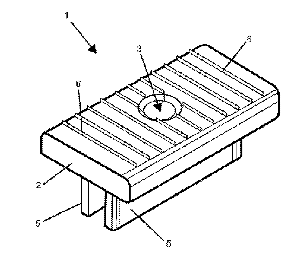
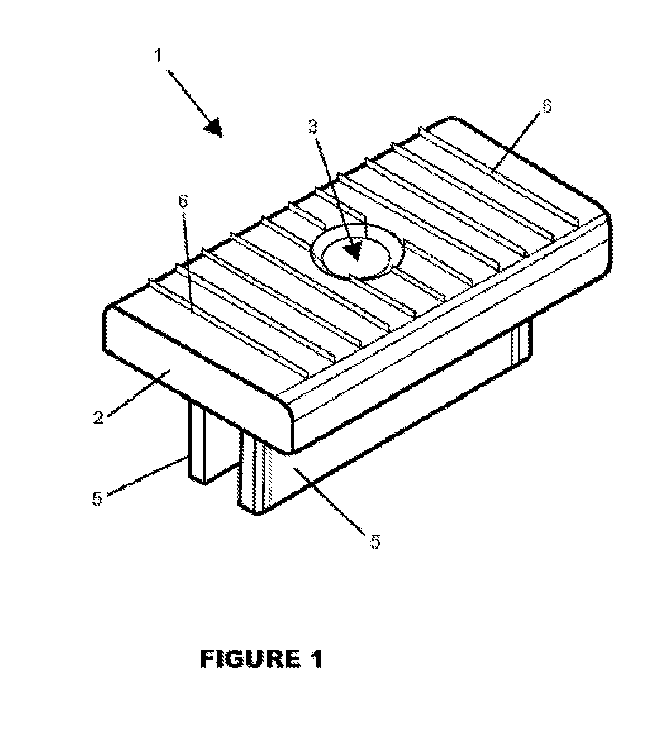
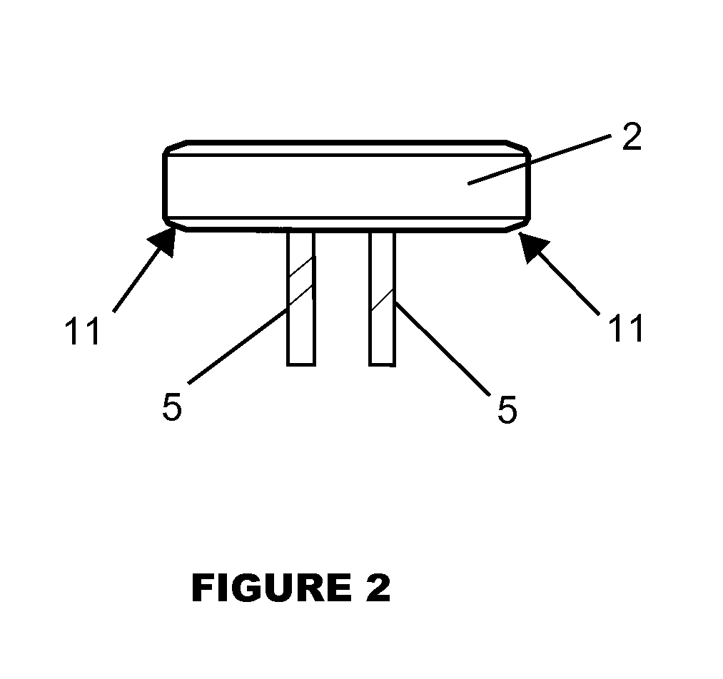
[0012]According to yet another object of the invention, the clip according to this invention is generally a Π-shaped clip device having a top horizontal portion and a pair of integrally formed spaced apart vertical legs underneath. The legs define a spacing distance across their span and are inwardly compressible toward each other in response to a side force. The top or bottom surface of the top portion has raised gripping means for frictionally engagement. The side edges of the horizontal portion are inserted into the grooves of adjacent structural members to abut against said legs to thereby engage and secure the structural members to a supporting structure separated from each other by the spacing distance.

Problems solved by technology

First, the fasteners are visible, unattractive and take away from the façade or look of the natural wood.
The fasteners may rust and discolor the structural members.
A fastener may work loose and become a safety hazard to persons walking on top of the supporting structure.
Finally, hammer blows to decking surface during installation of the fastener may cause damage and / or depressions that collect water.
The collection of water may lead to splintering of the structural members, mold growth and the propagation of cracks starting at where the fastener installation occurs.
Another problem associated with the above is the potential for error during installation of the structural members because the installer cannot see exactly where the joists lie underneath the structural member.
Resultantly, during installation of fasteners the installer may miss a joist or only partially strike a joist with the fastener and may have to back out the fastener or leave the fastener in the structural member and install yet another fastener to secure the structural member to the joist.
Another shortcoming is the potential for the structural members to loosen and move over time losing its uniform look resulting in loss of aesthetic appeal.

Method used


Image

  • Clip device for attaching structural member to a supporting structure
  • Clip device for attaching structural member to a supporting structure
  • Clip device for attaching structural member to a supporting structure

Examples


Embodiment Construction

[0019]Referring to FIG. 1, a generally Π-shaped clip device 1 according to the present invention is illustrated. The clip is intended to be used in conjunction with structural members 8 or planks which are manufactured with longitudinal grooves or slots 9 on each opposing side edge as shown in FIG. 5. As will be described hereafter, the clip device 1 is securely fastened to the surface of a supporting surface such as an underlying joist 10 and serves as an anchoring device to secure adjacent structural members 8 in place.

[0020]Referring to FIG. 3, grooves 9 are provided in the opposing side edges of the structural members 8. The groove has a thickness t and divides the side edge into a top and bottom edge portion. The groove functions to receive the clip during installation of the decking system. The structural members 8 may be manufactured from a non-wood material such as PVC or composite materials, or alternatively, traditional wood structural members modified with grooves may als...


PUM


Abstract

A Π-shaped clip with a top horizontal portion and a pair of integrally formed spaced apart vertical legs underneath. The legs define a spacing distance across their span and are inwardly compressible toward each other in response to a side force. The top portion has raised gripping means for frictional engagement. The clip is inserted into grooves of adjacent structural members secure them to a supporting structure.

Description

FIELD OF THE INVENTION[0001]The invention relates to an under deck fastening clip, system and method which can be used to “invisibly” attach a structural member to a supporting joist-like structure.BACKGROUND OF THE INVENTION[0002]There are a variety of decking systems on the market today. Most of the decking systems utilize some sort of fastening means to attach the structural members to the underlying joists such as a screw, nail or staple. Typically, the fastening means is installed directly through the top face of the structural members to the joist below.[0003]The common method of securing the structural members to the underlying joists by directly fastening the structural member to the joist through the top face of the structural member has many drawbacks. First, the fasteners are visible, unattractive and take away from the façade or look of the natural wood. The fasteners may rust and discolor the structural members. A fastener may work loose and become a safety hazard to pe...

Claims


Application Information

Patent Timeline
Patent Type & Authority Patents(United States)
IPC IPC(8): E04B1/38E04C5/00E04F15/02
CPCE04F15/02044E04F2015/02122
Inventor ORCHARD, BRIAN KEITH
Owner PAN AMERICAN SCREW
Learn More