Driving structure of electronic lock

a technology of electronic locks and driving structures, applied in the direction of latching locks, building locks, constructions, etc., can solve the problems of springs being susceptible to undesired deformation, unable to engage the mechanism, and losing resiliency, so as to achieve stable and reliable springs, not easy to deform and change shape, and strong flexibility

Inactive Publication Date: 2015-11-10
PENG FU CHANG
View PDF20 Cites 29 Cited by
  • Summary
  • Abstract
  • Description
  • Claims
  • Application Information

AI Technical Summary

Benefits of technology

[0011]With the improved valve having a robust structure and showing flexibility so as not to be easy to deform and change shape, and a separation plate being additionally provided inside the lock core to effectively separate an electronic valve and a spring to prevent interference with each other, advantages of extending lifespan and being not easy to damage are achieved.

Problems solved by technology

However, after having been long put in operation, the spring is susceptible to undesired deformation due to long compression by external forces and eventually loses the resiliency thereof.
The extension / retraction stroke of the valve would then be undesirably shortened, making it no longer possible to engage the mechanism.
Since the two members are located very close, the block often interferes with extension and retraction of the spring of the latch, leading to failure of unlocking or the latch being unable to return after being unlocked.

Method used


Image

  • Driving structure of electronic lock
  • Driving structure of electronic lock
  • Driving structure of electronic lock

Examples


Embodiment Construction

[0028]The following descriptions are exemplary embodiments only, and are not intended to limit the scope, applicability or configuration of the invention in any way. Rather, the following description provides a convenient illustration for implementing exemplary embodiments of the invention. Various changes to the described embodiments may be made in the function and arrangement of the elements described without departing from the scope of the invention as set forth in the appended claims.

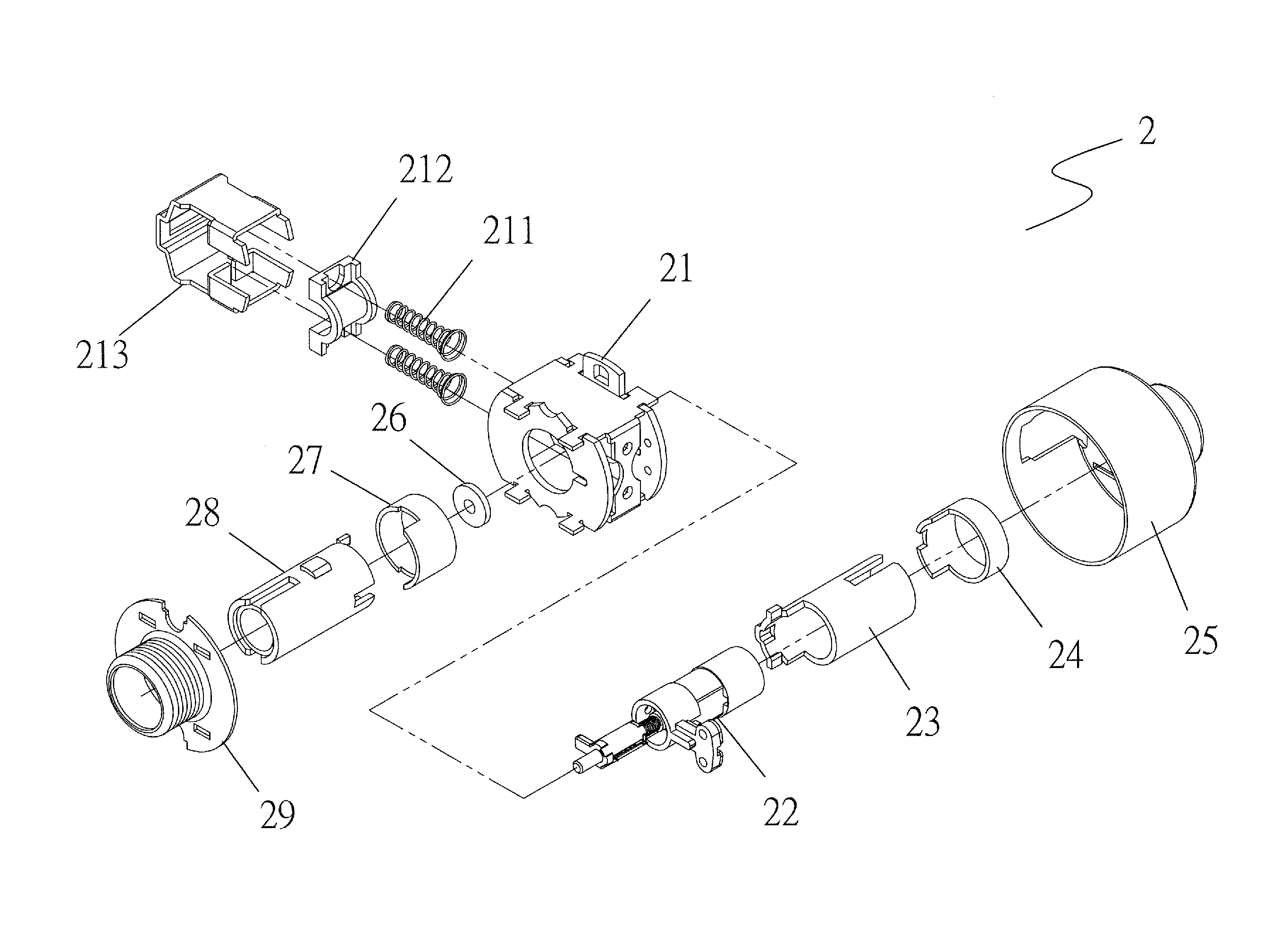
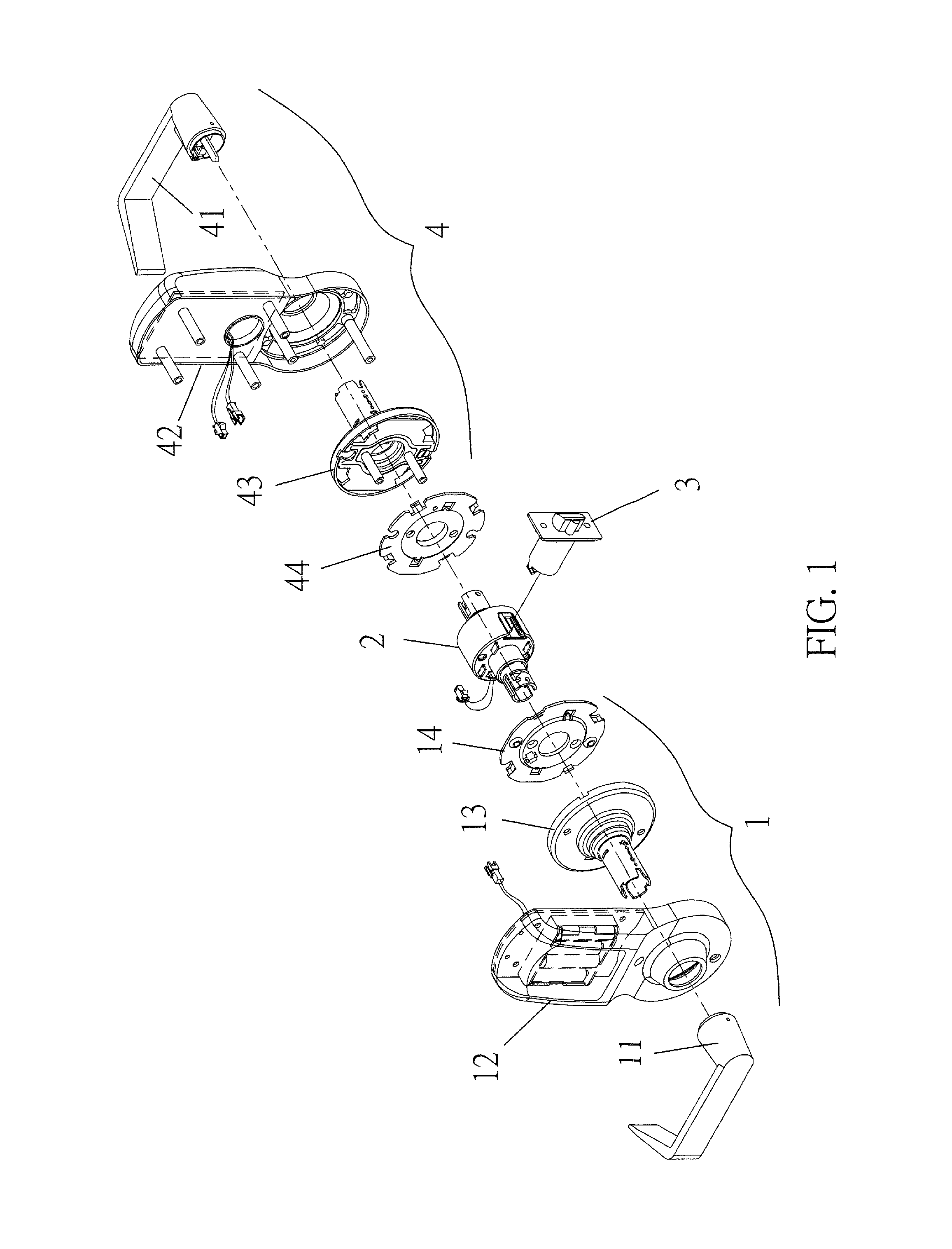
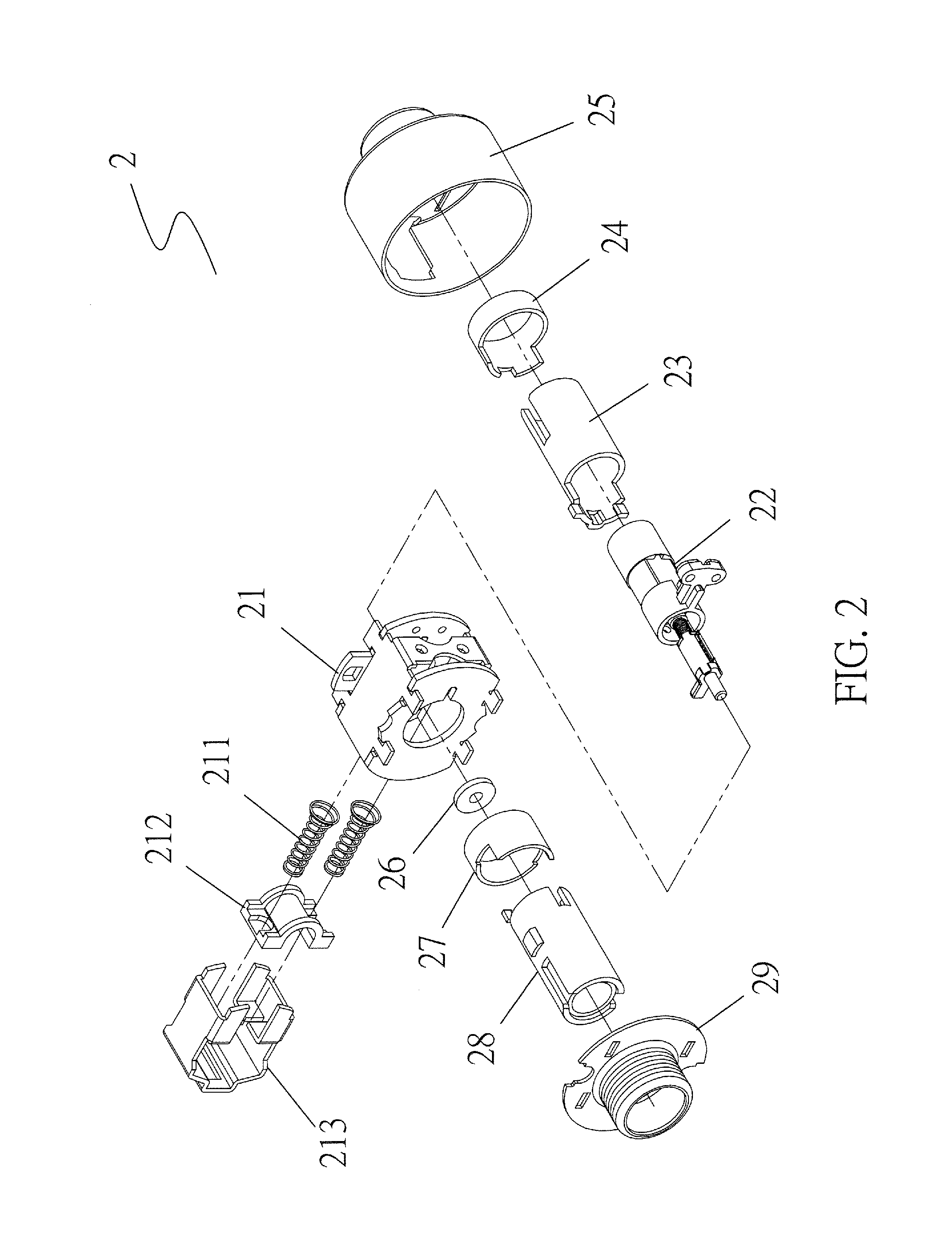
[0029]Referring to FIG. 1, an exploded view is given to illustrate an improved driving structure of an electronic lock according to the present invention, which comprises an outdoor assembly 1, a lock core 2, an indoor assembly 4, and a latch bolt 3. The outdoor assembly 1 is mounted to an outside surface of a door panel. The indoor assembly 4 is mounted to an inside surface of the door panel. The lock core 2 is arranged between the outdoor assembly 1 and the indoor assembly 4 and is coupled thereto...


PUM


Abstract

An improved driving structure of an electronic lock includes an outdoor assembly, a lock core, an indoor assembly, and a latch bolt. The outdoor assembly is mounted to an outside surface of a door panel. The indoor assembly is mounted to an inside surface of the door panel. The lock core is arranged between the outdoor assembly and the indoor assembly and coupled thereto. The lock core is operatively coupled to the latch bolt. As such, an improved structure of an electronic lock is constructed. When a user enters a correct combination of codes, the electrical valve of the lock core stretches the projection block outward to engage the second stopper so as to allow the exterior handle and the lock core to be operated synchronously for unlocking. Without the combination of codes, a key may be used to unlock the door.

Description

(a) TECHNICAL FIELD OF THE INVENTION[0001]The present invention generally relates to an electronic lock, and more particularly to an improved electronic lock driving structure that involves an improvement of a structure of a driving valve.(b) DESCRIPTION OF THE PRIOR ART[0002]A conventional electronic lock comprises a electrical valve that comprises a motor connected to a rotatable member including a thread and coupled to a spring having an end carrying a block. When the thread-included rotatable member is rotated, the spring is caused to move along a spring track for compression and extension of the spring in a backward and forward direction so that the block of the valve is stretched out to engage a mechanism. The operation is achieved by having the valve extending forward or retracting backward with the resiliency of the spring and the thread. However, after having been long put in operation, the spring is susceptible to undesired deformation due to long compression by external f...

Claims


Application Information

Patent Timeline
Patent Type & Authority Patents(United States)
IPC IPC(8): E05B47/00E05B63/08
CPCE05B47/0001E05B63/08E05B47/068E05B47/0012E05B55/005E05B2047/0031
Inventor PENG, FU-CHANG
Owner PENG FU CHANG
Why Eureka
Try Eureka