
Entrance security system

Active Publication Date: 2015-11-10
WOVEN ELECTRONICS
View PDF19 Cites 2 Cited by
  • Summary
  • Abstract
  • Description
  • Claims
  • Application Information

AI Technical Summary

Benefits of technology

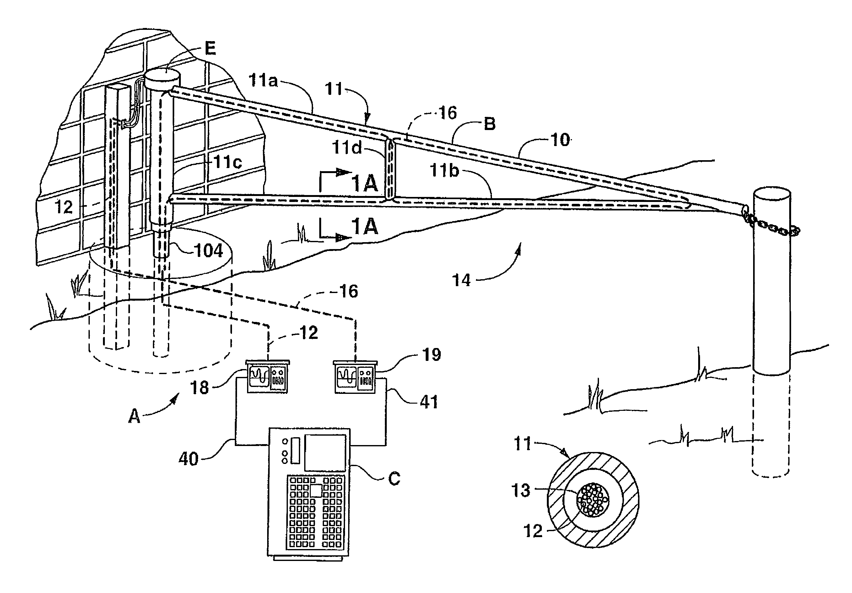
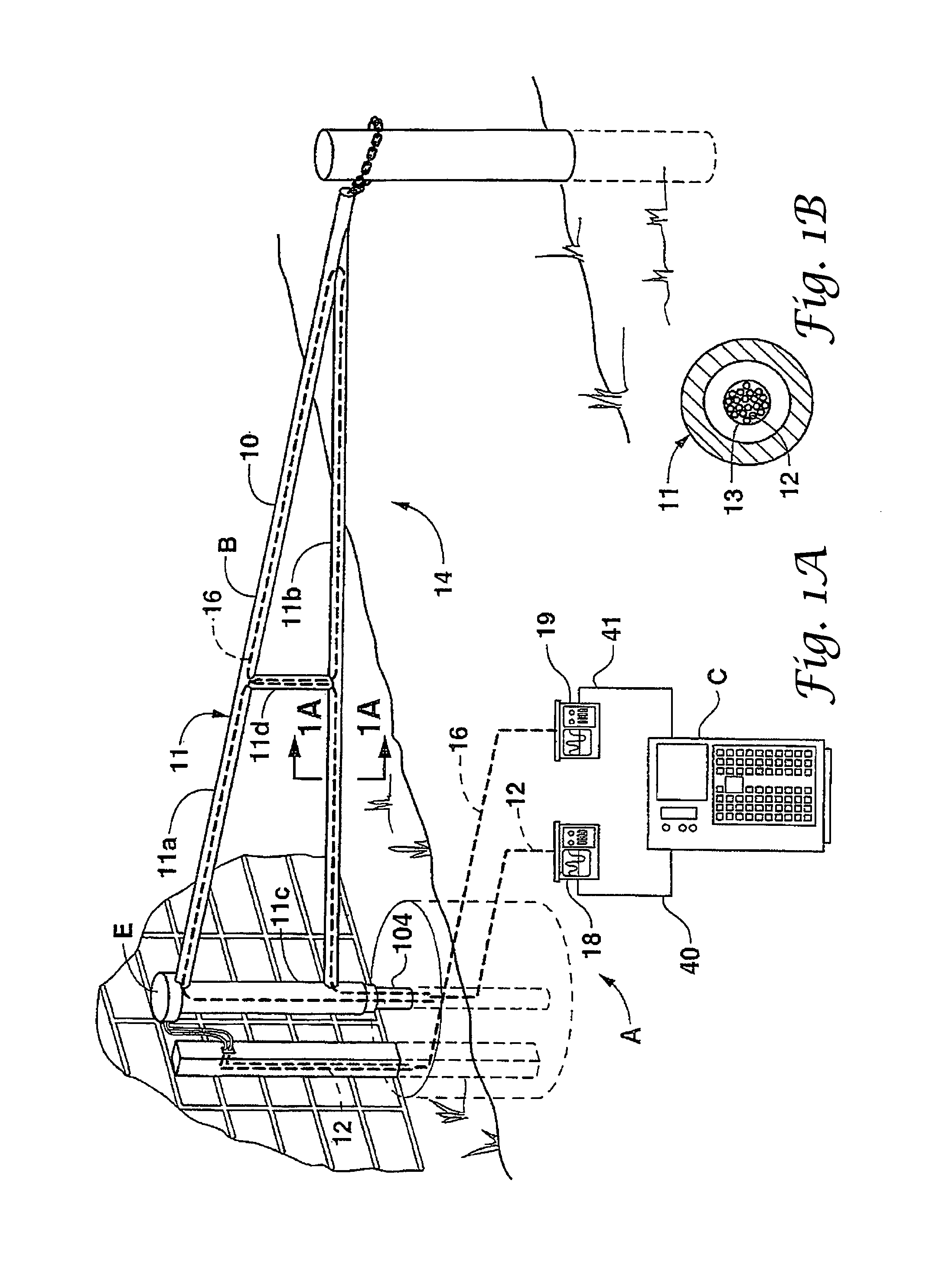
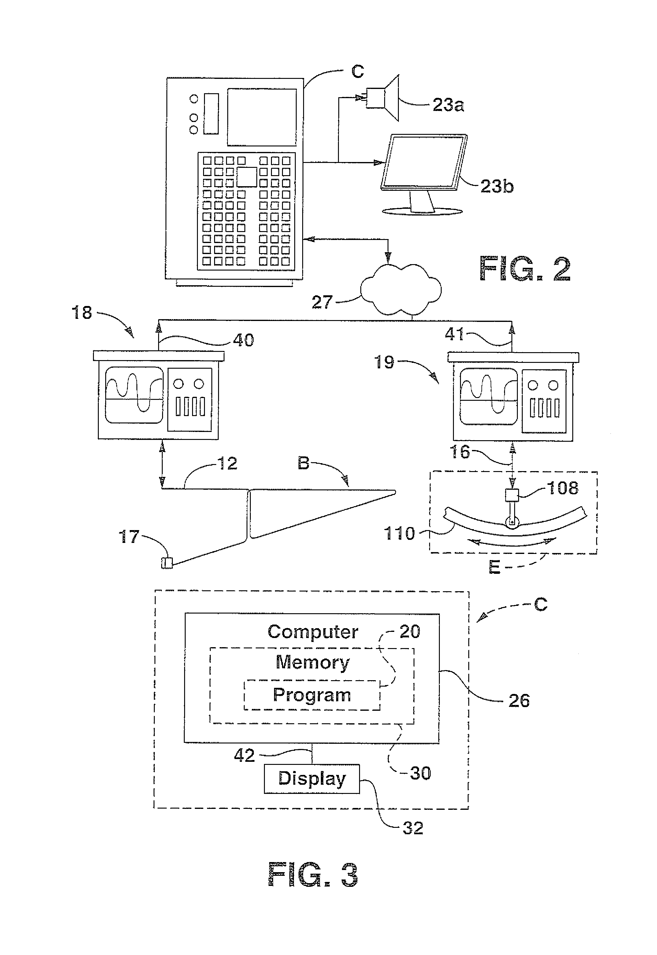
The present invention is a security system for detecting unauthorized activity and attempt to enter through an entrance of a secured area and determining the nature and location of the activity. The system includes an entrance barrier with hollow structural elements forming an integral barrier structure such as an entrance gate (or fixed barrier) and fiber optic sensor lines sensing a first fault condition representing an unauthorized attempt to open the gate and a severance of a structural element of the barrier. The system also includes a longitudinal reinforcing member in the form of a solid stainless steel rod enclosed in the tubular elements along with the sensor lines which must be severed before intrusion. The system computer receives and processes the scan signals in real-time representing the condition of the optical sensor lines and generates a real-time fault signal in response to a predetermined reflection in one or more of the scan signals indicating the unauthorized activity has occurred. The communication device communicates notice of the fault signal to security personnel. The method involves reinforcing the tubular elements with a solid metal rod that delays cut through of the tubular elements until after the sensor line is cut and a fault signal generated. The method includes generating real-time scan signals in the fiber sensor line sensing the current state of the fiber sensor line, processing the scan signals to establish a baseline signal from the sensor line representing an undisturbed state of the optical fiber sensor line, comparing the scan signals to the baseline signal, and alerting personnel of the fault condition. The technical effect of the invention is to provide an effective security system for detecting and preventing unauthorized entry through an entrance of a secured area and determining the nature and location of the activity.

Problems solved by technology

With the increase in terrorism in the United States and the rest of the world, the need for an effective security system to detect and / or prevent the unauthorized entry of a vehicle and / or individual from breaking through a barrier closing an entrance into a secured area is a problem to which considerable attention needs to be given.

Method used


Image

  • Entrance security system
  • Entrance security system
  • Entrance security system

Examples


Embodiment Construction

[0044]The present invention is now described more fully herein with reference to the drawings in which the preferred embodiment of the invention is shown. This invention may, however, embody other forms and should not be construed as limited to the embodiment set forth herein. Rather, these embodiments are provided so that this disclosure will be thorough and complete and will fully convey the scope of the invention to those skilled in the art.

[0045]The detailed description of some of the components that follow may be presented in terms of steps of methods or in program procedures executed on a computer or network of computers. These procedural descriptions are representations used by those skilled in the art to most effectively convey the substance of their work to others skilled in the art. These procedures herein described are generally a self-consistent sequence of steps leading to a desired result. These steps require physical manipulations of physical quantities such as electr...


PUM


Abstract

An entrance denial security system comprises an entrance barrier closing an entrance into a secured area having a plurality of structural tubular elements with hollow cores forming a rigid integral barrier. At least one optical fiber sensor line is laced through the hollow cores of the structural elements for detecting a fault condition signifying an unauthorized intrusion attempt. A processor in communication with the fiber sensor line generates a fault signal in response to a fault signal level. A communication device operatively associated with the processor communicates the fault signal and an alarm. The system also includes a plurality of tubular elements lying a common plane and the sensor line is routed through the tubular elements. In one instance, the tubular elements are PVC pipe.

Description

CROSS REFERENCE TO RELATED APPLICATIONS[0001]This application claims priority from U.S. provisional application no. 60 / 456,687, filed Mar. 15, 2003, entitled “Fiber Optic Security System For Sensing the Intrusion Of Secured Locations,” U.S. non-provisional application Ser. No. 10 / 429,602, filed May 5, 2003, entitled “Fiber Optic Security System For Sensing Intrusion Of Secured Locations;” PCT application no. PCT / US2004 / 013494, filed May 3, 2004, entitled “Fiber Optic Security System For Sensing The Intrusion Of Secured Locations;” U.S. provisional application No. 60 / 626,197, filed Nov. 9, 2004, entitled “Vehicle Denial Security System;” U.S. non-provisional application Ser. No. 11 / 083,038, filed Mar. 17, 2005, entitled “Apparatus And Method For A Computerized Fiber Optic Security System;” now U.S. Pat. No. 7,800,047 issued Sep. 21, 2010; U.S. provisional application No. 60 / 673,699, filed Apr. 21, 2005, entitled Secure Above Ground Fiber Optic Data Transmission Cable;” PCT applicatio...

Claims


Application Information

Patent Timeline
IPC IPC(8): G08B13/00G08B13/186G08B13/12A61B1/00H01L21/00
CPCG08B13/186A61B1/00G08B13/124H01L21/00
Inventor PIPER, SR., DOUGLAS E.BROWNING, JR., THOMAS E.OWENS, MARY HESTERDEYOUNG, CLIFFORD LEROYSHASTEEN, SAM SNEADPHILLIPS, MARK C.
Owner WOVEN ELECTRONICS
Features
  • Generate Ideas
  • Intellectual Property
  • Life Sciences
  • Materials
  • Tech Scout
  • Unparalleled Data Quality
  • Higher Quality Content
  • 60% Fewer Hallucinations
Learn More