Entrance security system

Active Publication Date: 2010-02-18
WOVEN ELECTRONICS
View PDF6 Cites 4 Cited by
  • Summary
  • Abstract
  • Description
  • Claims
  • Application Information

AI Technical Summary

Benefits of technology

[0002]This invention relates to an entry denial security system for denying entry of a vehicle or person into a secured area and/or detecting an attempt to penetrate a barrier closing an entrance into the secured area.
[0003]With the increase in terrorism in the United States and the rest of the world, the need for an effective security system to detect and/or prevent the unauthorized entry of a vehicle and/or individual from breaking through a barrier closing an entrance into a secured area is a problem to which considerable attention needs to be given. In particular, an objective of this invention is to provide an entrance security system which detects an unauthorized opening or break through of an entrance barrier closing an entrance of the secured area.
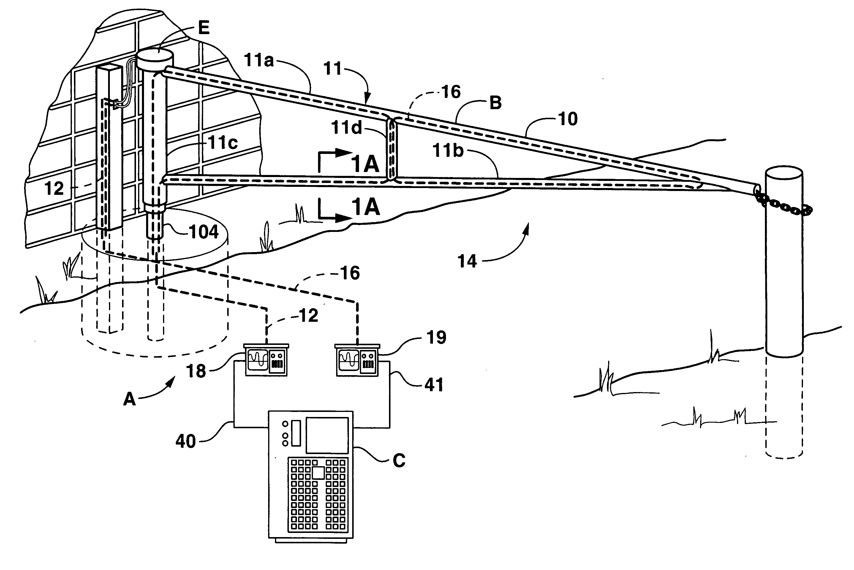
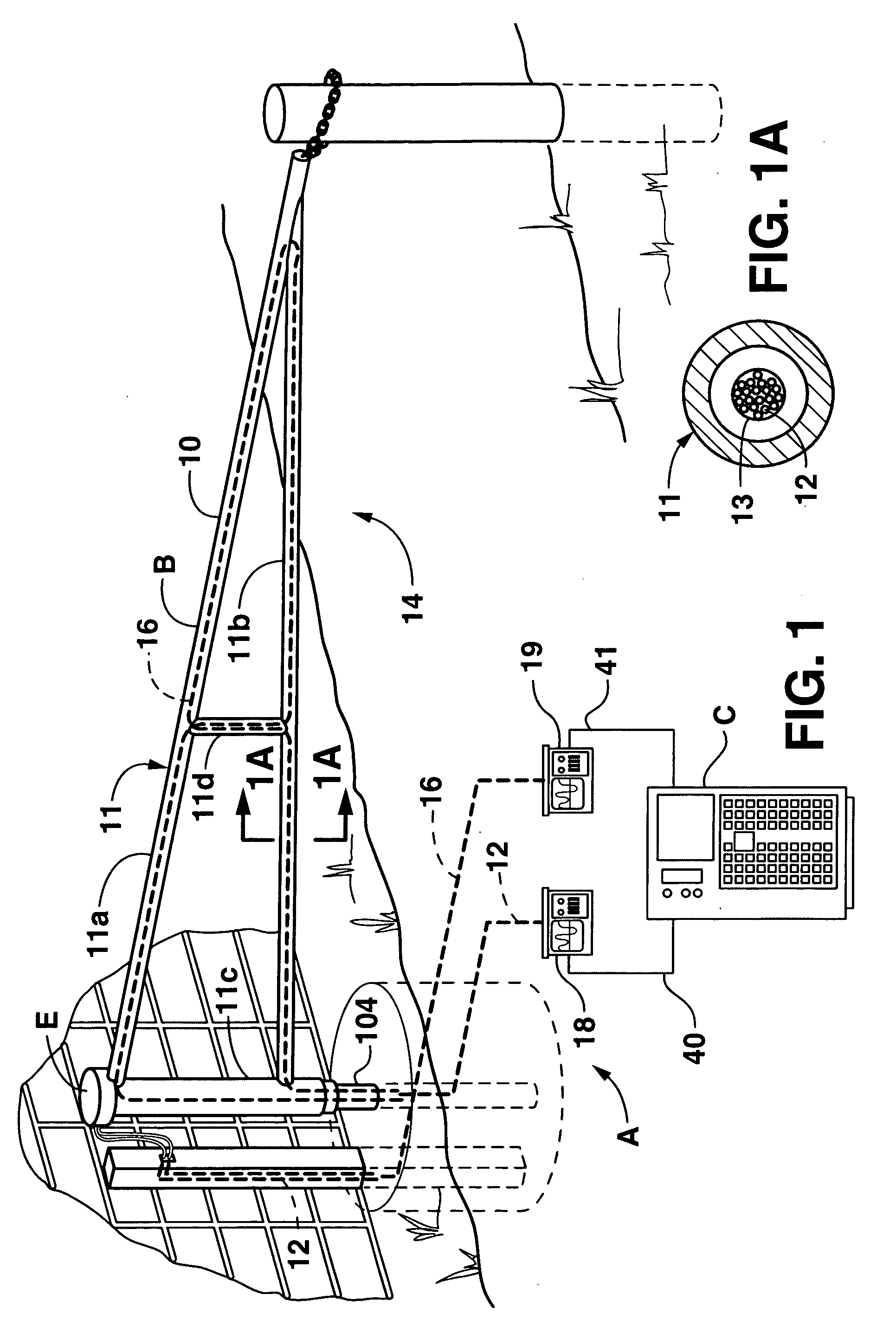
[0004]The above objectives are accomplished according to the present invention by providing a security system for detecting an unauthorized activity and attempt to enter through an entrance of a secured area and determining the nature and location of the activity. The security system comprises an entrance barrier closing the entrance, including a plurality of hollow structural elements forming an integral barrier structure such as an entrance gate (or fixed barrier). Preferably, fiber optic sensor lines

Problems solved by technology

With the increase in terrorism in the United States and the rest of the world, the need for an effective security system to detect and/or prevent the unauthorized entr

Method used


Image

  • Entrance security system
  • Entrance security system
  • Entrance security system

Examples


Embodiment Construction

[0034]The present invention is now described more fully herein with reference to the drawings in which the preferred embodiment of the invention is shown. This invention may, however, embody other forms and should not be construed as limited to the embodiment set forth herein. Rather, these embodiments are provided so that this disclosure will be thorough and complete and will fully convey the scope of the invention to those skilled in the art.

[0035]The detailed description of some of the components that follow may be presented in terms of steps of methods or in program procedures executed on a computer or network of computers. These procedural descriptions are representations used by those skilled in the art to most effectively convey the substance of their work to others skilled in the art. These procedures herein described are generally a self-consistent sequence of steps leading to a desired result. These steps require physical manipulations of physical quantities such as electr...


PUM


Abstract

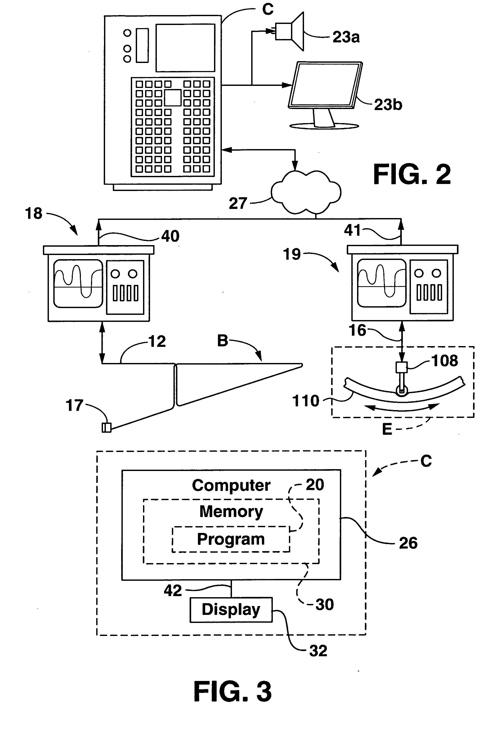
An entrance denial security system comprises an entrance barrier closing an entrance into a secured area having a plurality of structural tubular elements with hollow cores forming a rigid integral barrier. At least one optical fiber sensor line is laced through the hollow cores of the structural elements for detecting a fault condition signifying an unauthorized intrusion attempt. A processor in communication with the fiber sensor line generates a fault signal in response to the occurrence of a fault condition and identifying the entrance where the fault condition occurred. A communication device operatively associated with the processor communicates the fault signal and an alarm so that a proper security response can be made to the fault condition. The system further comprises a plurality of intrusion sensors disposed at certain locations. Preferably primary and secondary optical fiber sensor lines are routed through the structural elements and intrusion sensors, and primary and secondary scanning units pulse signals along the sensor lines and receive reflected signals back from the sensor lines. In the event of a cut through in the sensor lines, the primary sensor line monitors the barrier and sensors downstream of the break, and the secondary sensor line is activated to monitor the barriers and sensors downstream of the break.

Description

CROSS REFERENCE TO RELATED APPLICATIONS[0001]This application claims priority from U.S. provisional application No. 60 / 456,687, filed Mar. 15, 2003, entitled “Fiber Optic Security System For Sensing the Intrusion Of Secured Locations,” U.S. non-provisional application Ser. No. 10 / 429,602, filed May 5, 2003, entitled “Fiber Optic Security System For Sensing Intrusion Of Secured Locations;” PCT application no. PCT / US2004 / 013494, filed May 3, 2004, entitled “Fiber Optic Security System For Sensing The Introduction Of Secured Locations;” U.S. provisional application No. 60 / 626,197, filed Nov. 9, 2004, entitled “Vehicle Denial Security System;” U.S. non-provisional application Ser. No. 11 / 083,038, filed Mar. 17, 2005, entitled “Apparatus And Method For A Computerized Fiber Optic Security System;” U.S. provisional application No. 60 / 673,699, filed Apr. 21, 2005, entitled “Secure Above Ground Fiber Optic Data Transmission Cable;” PCT application no. PCT / US2005 / 040079, filed Nov. 4, 2005, e...

Claims


Application Information

Patent Timeline
IPC IPC(8): G08B13/18
CPCG07C9/00571G08B13/186G08B13/124G08B13/08
Inventor PIPER, DOUGLAS E.BROWNING, THOMAS E.OWENS, MARY HESTERDEYOUNG, CLIFFORD LEROY
Owner WOVEN ELECTRONICS
Why Eureka
Try Eureka