Advanced warning system for emergency vehicles

Inactive Publication Date: 2007-11-29
JACOBS ROYCE A +1
5 Cites 18 Cited by

AI-Extracted Technical Summary

Problems solved by technology

Unfortunately, the use of helicopters to respond to all emergencies is not only impractical but they are also costly.
Oftentimes the response time for emergency vehicles are further delayed by vehicular congestion on the roads, especially during rush hour.
Although, motorists are aware that they need to clear a path for the emergency vehicle they may not be able to do so because of the congestion.
However, it is not uncommon for motorists to be distracted b...

Method used

[0031]If the non-emergency vehicle is within a certain distance or radius that closely approximates imminent approach of the emergency vehicle, i.e. a critical zone, the alarm generating means 106 will trigger the non-emergency vehicle's alarm to flash red as in Step 210. In addition, the alarm will interrupt all audible transmissions to broadcast a command message for e.g. “WARNING, EMERGENCY VEHICLE IS IMMIN...

Benefits of technology

[0008]Generally, the objective of this present invention is to provide an advanced warning system that will alert motorists of an approaching emergency vehicle to provide motorists with ample time to yield the right of way and clear a path for the emergency vehicle, thereby drastically reducing the emergency vehicle's response time. The present invention comprises of two major components—a transmitter and a receiver component (also referred to herein as the “Interface Module”). The transmitter component comprises of transmitting ...

Abstract

An advanced warning system that will alert motorists of an approaching emergency vehicle to provide motorists with ample time to yield the right of way and clear a path for the emergency vehicle, thereby drastically reducing the emergency vehicle's response time.

Application Domain

Technology Topic

EngineeringEmergency vehicle +2

Image

  • Advanced warning system for emergency vehicles
  • Advanced warning system for emergency vehicles
  • Advanced warning system for emergency vehicles

Examples

  • Experimental program(1)

Example

[0020]The present invention is now described in more detail by reference to the exemplary drawings in detail wherein like numerals indicate like elements throughout the various views. This is for convenience only and is not intended to limit the application of the present invention. In fact, after reading the following description, it will be apparent to one skilled in the relevant art(s) how to implement the following invention in alternate embodiments.
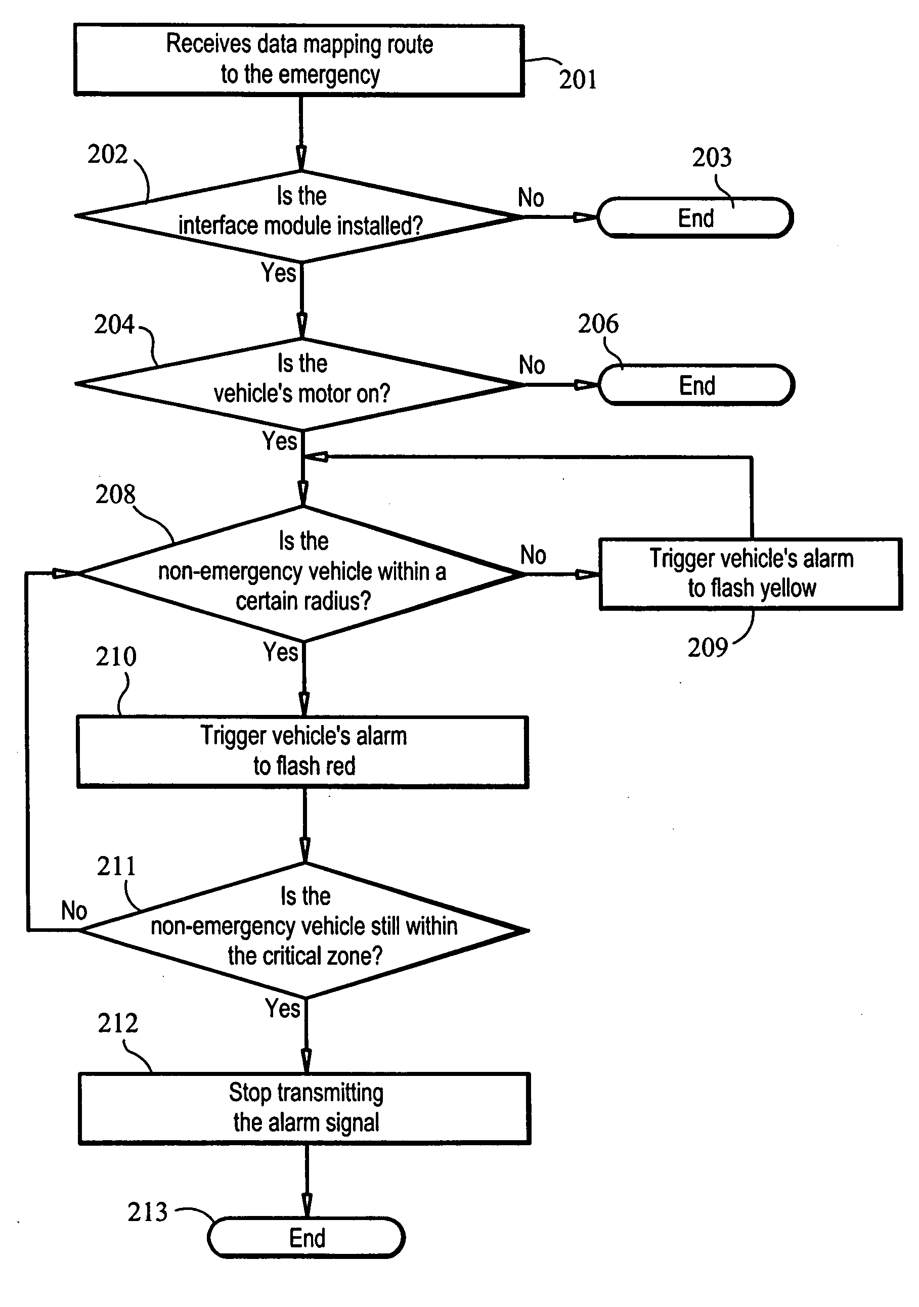
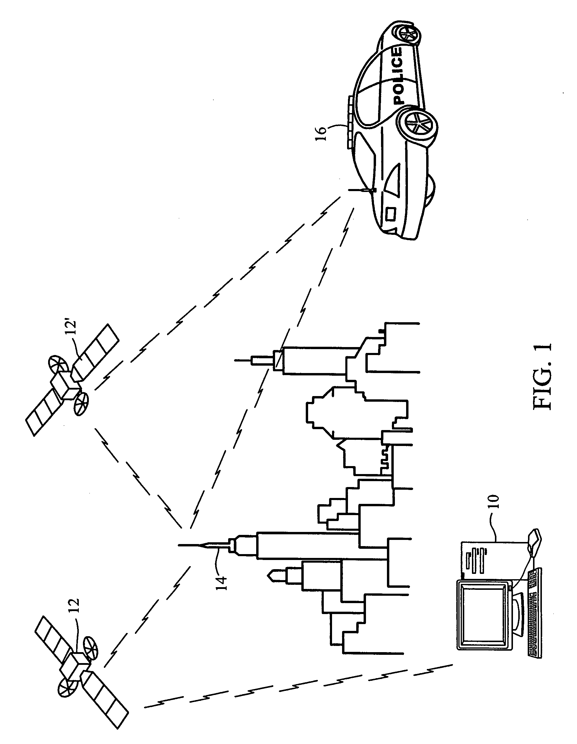
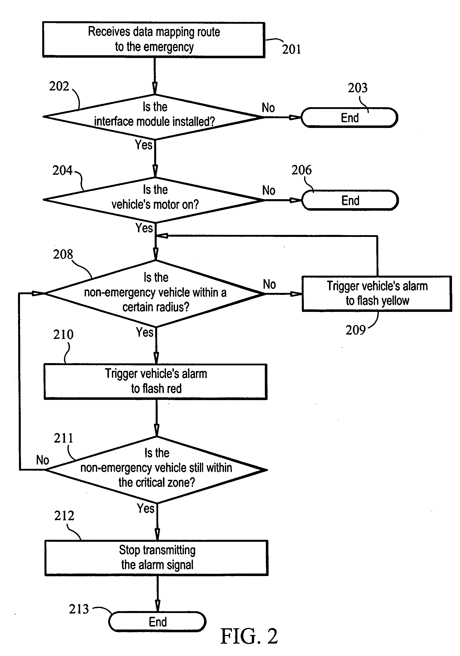
[0021]The present invention comprises of two major components—transmitter component 10 and an Interface Module 22. The transmitter component 10 further comprises of transmitting means 102 for transmitting and receiving information to or from satellites and or other communication devices; a signal generation means 104 for generating signals; an alarm generating means 106 for activating and controlling alarms in non-emergency vehicles equipped with the Interface Module 22; and a location determining means 108 for determining the location of non-emergency vehicles. In one embodiment of the invention, the location determining means 108 may determine the location of non-emergency vehicles relative to the emergency. In an alternate embodiment of the invention, the location determining means 108 may determine the location of non-emergency vehicles relative to the emergency vehicle. These elements of the transmitter component 10 may be in communication with each other in a variety of ways known to those of ordinary skill in the art including, but not limited to, wireless connections. The Interface Module 22 comprises of receiving means 24 for receiving generated signals and a second signal generation means 26 for generating and relaying signals to the transmitter component 10 of the invention.
[0022]Generally, in the case of an emergency, the authorities are first notified by a telephone call through a 911 operator. Depending on the type of emergency, the 911 operator will determine whether a fire truck, police, ambulance or some combination thereof, will be the appropriate response and will route the request for emergency services accordingly.
[0023]FIG. 1 is a schematic illustration of the elements and entities involved in the emergency response system in accordance with an exemplary embodiment of the present invention. As seen in FIG. 1, once the advanced warning system for emergency vehicles 100 receives information concerning the location and nature of the emergency, i.e. fire, crime or health incident, the transmitter component 10 of the system transmits that information to a GPS satellite system 12, 12′.
[0024]The GPS receivers 13 (not shown) in combination with GPS satellite system 12, 12′ receives the transmitted information and use triangulation to calculate inter alia, the emergency response team's precise location, distance to the destination location, i.e. the emergency site, and the fastest route to the emergency. In urban areas, emergency response teams would most likely rely on Differential GPS (DGPS) to provide signal correction in areas with several skyscrapers as the DGPS receivers are much more accurate than ordinary receivers.
[0025]As seen in FIG. 1, the GPS satellite system 12, 12′ broadcasts the GPS signal to a ground receiver 14, which interprets the data and transmits the information to a GPS receiver in the emergency vehicle 16 that displays the data on an electronic map 18 (not shown). As is well known and used in the art, many GPS receivers that are installed in motorvehicles are equipped with an audio component providing the driver with precise and detailed audible navigational instructions to the destination location.
[0026]FIG. 2 is a flow chart illustrating the tasks performed by the advanced warning system for emergency vehicles 100 as it involves a response to an emergency. Once the advanced warning system for emergency vehicles 100 receives data from the GPS satellite system 12, 12′ mapping the route to the emergency as shown in Step 201, using the signal generating means 104, the transmitter component 10 generates a first request signal that automatically polls non-emergency vehicles within a certain radius or distance detected to be en route to the emergency, to confirm whether or not the non-emergency vehicle has the corresponding Interface Module 22 of the invention installed as shown in Step 202.
[0027]If the non-emergency vehicle is not equipped with the Interface Module 22 of the invention, then the transmitter component 10 of the system ignores that vehicle and no further signals or requests will be issued to that non-emergency vehicle as in Step 203. However, the transmitter component 10 of the invention will continue to poll all other vehicles within the specified radius and/or distance for similar information (Step not shown).
[0028]In the alternative, if the non-emergency vehicle is equipped with the Interface Module 22, the transmitter component 10 of the system, using the signal generating means 104, issues a second signal to the receiving means 24 of the Interface Module 22 of the non-emergency vehicle which receives the signal. The transmitter component 10 checks to see if the non-emergency vehicle is moving or parked by inquiring whether the non-emergency vehicle's motor is on as in Step 204 or off. If the individual vehicle's motor is off, the second signal generating means 26 of the Interface Module 22 will generate and relay a signal to the transmitter component 10 notifying the transmitter component 10 that the vehicle's motor is off as in Step 205 (not shown). Additionally, that non-emergency vehicle is ignored, and no further signals will be transmitted as in Step 206 to that non-emergency vehicle. If the non-emergency vehicle's motor is on, the second signal generation means 26 of the Interface Module 22 of the non-emergency vehicles will relay an additional signal confirming that the non-emergency vehicle is in motion to the transmitter component 10 as in Step 207 (not shown).
[0029]Once the transmitter component 10 receives confirmation from the second signal generation means 26 of the Interface Module 22 that the non-emergency vehicle is in motion, the location determining means 108 transmits a signal requesting verification from the Interface Module 22 that the non-emergency vehicle is within a certain prescribed radius and/or distance (Step 208) away from the emergency vehicle.
[0030]If the location determining means 108 detects that the non-emergency vehicle is within a certain prescribed range and/or radius from the emergency vehicle, e.g. half of a mile away, the alarm generating means 106 will trigger the non-emergency vehicle's alarm to flash yellow as in Step 209. For non-emergency vehicles equipped with the invention, the audio alarm will interrupt all audible transmissions to broadcast a corresponding warning message, e.g. “EMERGENCY VEHICLE WILL APPROACH SHORTLY” or some other words of similar import and/or content. The location determining means 108 will continue to confirm and verify that the non-emergency vehicle is still within that radius and/or distance by returning to Step 208 until the location determining means 108 is otherwise informed.
[0031]If the non-emergency vehicle is within a certain distance or radius that closely approximates imminent approach of the emergency vehicle, i.e. a critical zone, the alarm generating means 106 will trigger the non-emergency vehicle's alarm to flash red as in Step 210. In addition, the alarm will interrupt all audible transmissions to broadcast a command message for e.g. “WARNING, EMERGENCY VEHICLE IS IMMINENTLY APPROACHING” or similar words to that effect as in Step 214 (not shown). Accordingly, the non-emergency vehicle in this critical zone is alerted that there is an emergency vehicle that is imminently approaching. By having an early alert of the approaching emergency vehicle, non-emergency vehicles can create a clear path for the responding emergency vehicle allowing a more rapid response to the emergency.
[0032]If the non-emergency vehicle is still within the critical zone the location determining means 108 will return to Step 208 and continue to verify that the non-emergency vehicle is within the prescribed radius or distance and has not moved beyond that radius or distance. As such, the alarm signal is perpetuated until the location determining means 108 is otherwise notified. Once the non-emergency vehicle is outside the critical zone, the alarm generating means will stop transmitting the alarm signals to the non-emergency vehicles as in Step 212 and there will be no further transmissions to that non-emergency vehicle as in Step 213.

PUM

no PUM

Description & Claims & Application Information

We can also present the details of the Description, Claims and Application information to help users get a comprehensive understanding of the technical details of the patent, such as background art, summary of invention, brief description of drawings, description of embodiments, and other original content. On the other hand, users can also determine the specific scope of protection of the technology through the list of claims; as well as understand the changes in the life cycle of the technology with the presentation of the patent timeline. Login to view more.

Similar technology patents

Aggregation handling

ActiveUS10318446B2Reduce response timeEfficiently solveProgram controlReal-time computingMethod access
Owner:IBM CORP

Liquid crystal panel, liquid crystal display device and method for improving liquid crystal rotation obstacle

ActiveUS20180217419A1Reduce response timeImprovement of switchNon-linear opticsBody regionLiquid-crystal display
Owner:WUHAN CHINA STAR OPTOELECTRONICS TECH CO LTD

Read-ahead on signed connections with unsigning, inline, transparent proxies

ActiveUS20170041431A1Reduce response timeCode conversionTransmissionClient-sideServer agent
Owner:SONICWALL US HLDG INC

Optical touch panel device and recording medium

InactiveUS20150097813A1Control power consumptionReduce response timeInput/output processes for data processingOptical pathTouch panel
Owner:SHARP KK

Classification and recommendation of technical efficacy words

  • Ample time
  • Reduce response time

Entrance security system

ActiveUS20100039261A1Considerable attentionAmple timeRadiation pyrometryBurglar alarm by openingHollow coreEmbedded system
Owner:WOVEN ELECTRONICS

Ostomy Pouch Replacement Device

ActiveUS20190262167A1Ample timeColostomySuper absorbentUrine
Owner:STOMAGIENICS INC

Incremental erasing of flash memory to improve system performance

InactiveUS20060053247A1Reduce response timeRead-only memoriesMemory systemsMemory controllerFlash memory controller
Owner:TEXAS INSTR INC

LCD overdrive table triangular interpolation

InactiveUS20050146495A1Reduce response timeStatic indicating devicesFrame timeAlgorithm
Owner:GENESIS MICROCHIP

Electronic Thermometer with Selectable Modes

ActiveUS20080112461A1Reduce response timeIncrease precisionRadiation pyrometryThermometers using electric/magnetic elementsOperation modePrediction algorithms
Owner:CARDINAL HEALTH IRELAND UNLTD
Why Eureka
Try Eureka