
Single camera video-based speed enforcement system with a secondary auxiliary RGB traffic camera

a technology of video-based speed enforcement and traffic cameras, applied in closed-circuit television systems, road vehicle traffic control, instruments, etc., can solve the problems of large estimation error of systems with such wide fov in speed estimation tasks, limited ability of conventional single camera systems to accurately detect vehicle speed, etc., to achieve the effect of facilitating video-based speed estimation

Active Publication Date: 2015-11-10
CONDUENT BUSINESS SERVICES LLC
View PDF4 Cites 3 Cited by
  • Summary
  • Abstract
  • Description
  • Claims
  • Application Information

AI Technical Summary

Benefits of technology

The system achieves accurate and cost-effective vehicle speed estimation with improved evidentiary photo quality, reducing computational requirements and operational costs, while maintaining surveillance capabilities.

Problems solved by technology

Conventional single camera systems are hindered by limited abilities to accurately detect vehicle speed due to limitations associated with viewing a 3D world with 2D imaging devices.
Additionally, the quality of evidentiary photos provided by such systems is unsatisfactory due to the retro-reflective properties of license plates, which requires a sensor operating at high dynamic range at night.
Moreover, the camera field of view (FOV) conventionally is calibrated for speed detection accuracy, which conflicts with larger FOV requirements in traffic monitoring and incident detection.
The performance of systems with such wide FOV in speed estimation tasks typically exhibits a large degree of estimation error unless additional elements and / or features are included, such as multi-view capabilities, structured illumination, stereo-vision, etc.
These FOV problems cannot be easily solved with a conventional speed camera.
For instance, using such systems, the estimated speed is not accurate due to ambiguities introduced by mapping a 3D scene onto a 2D image.

Method used


Image

  • Single camera video-based speed enforcement system with a secondary auxiliary RGB traffic camera
  • Single camera video-based speed enforcement system with a secondary auxiliary RGB traffic camera
  • Single camera video-based speed enforcement system with a secondary auxiliary RGB traffic camera

Examples


Embodiment Construction

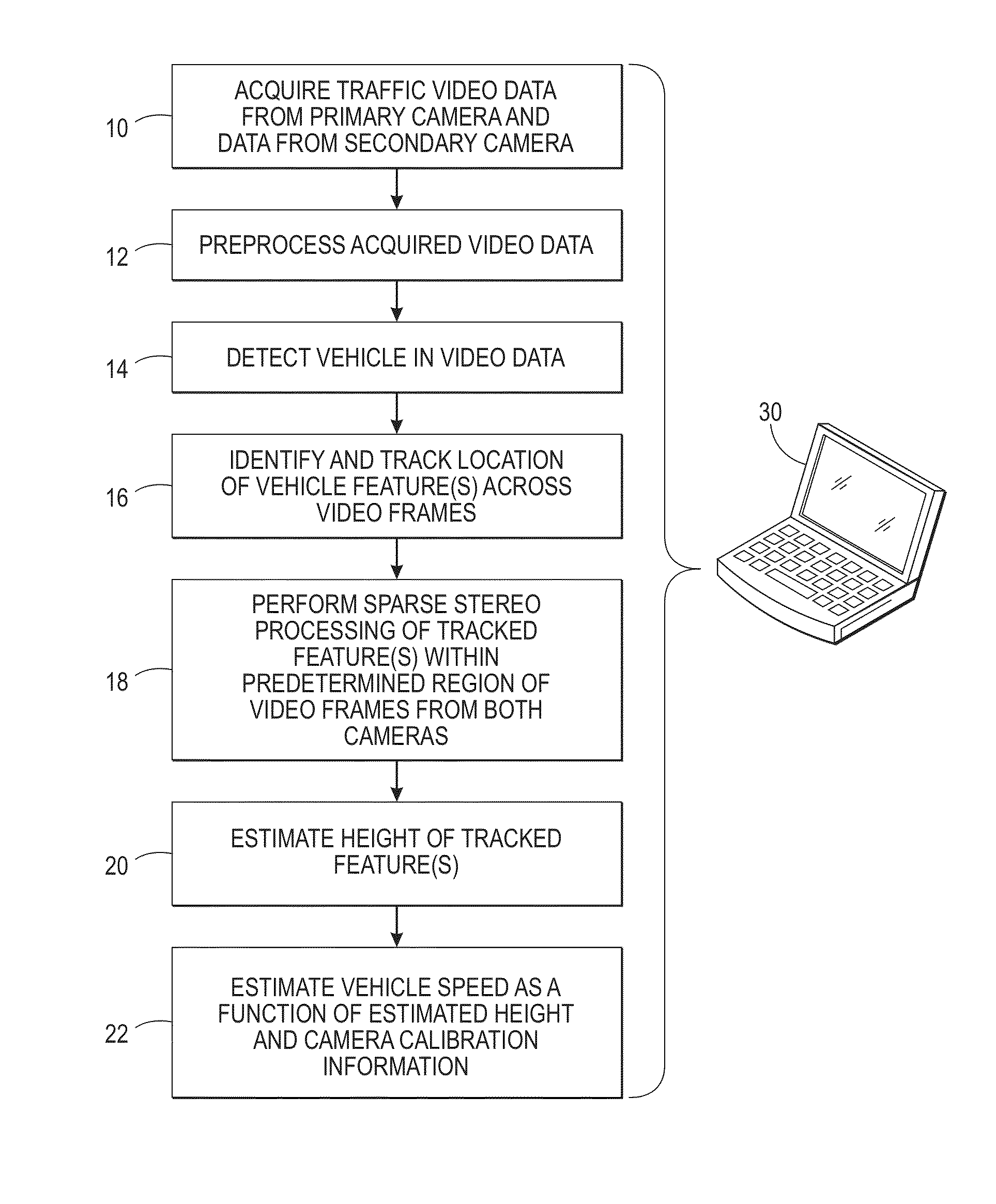
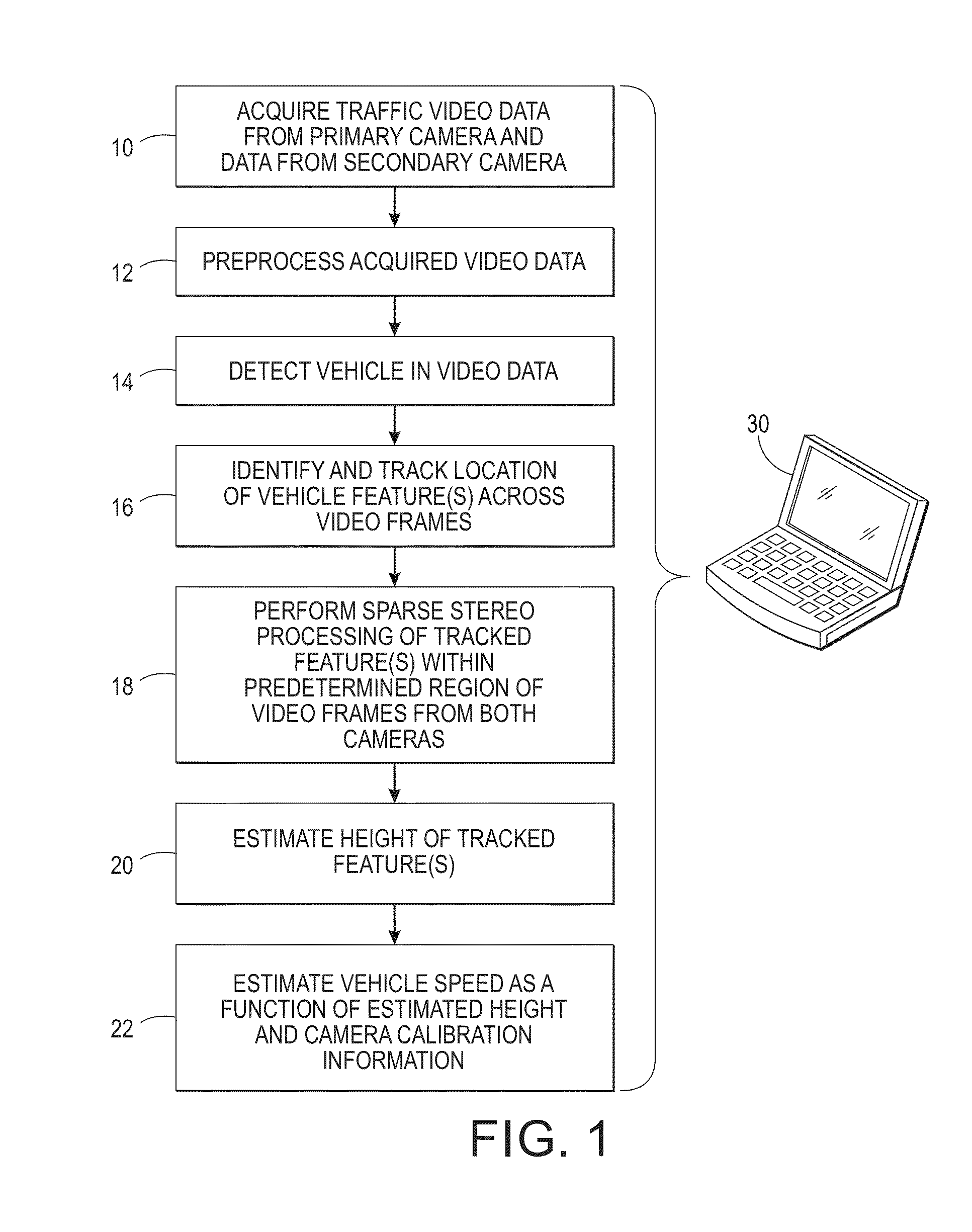
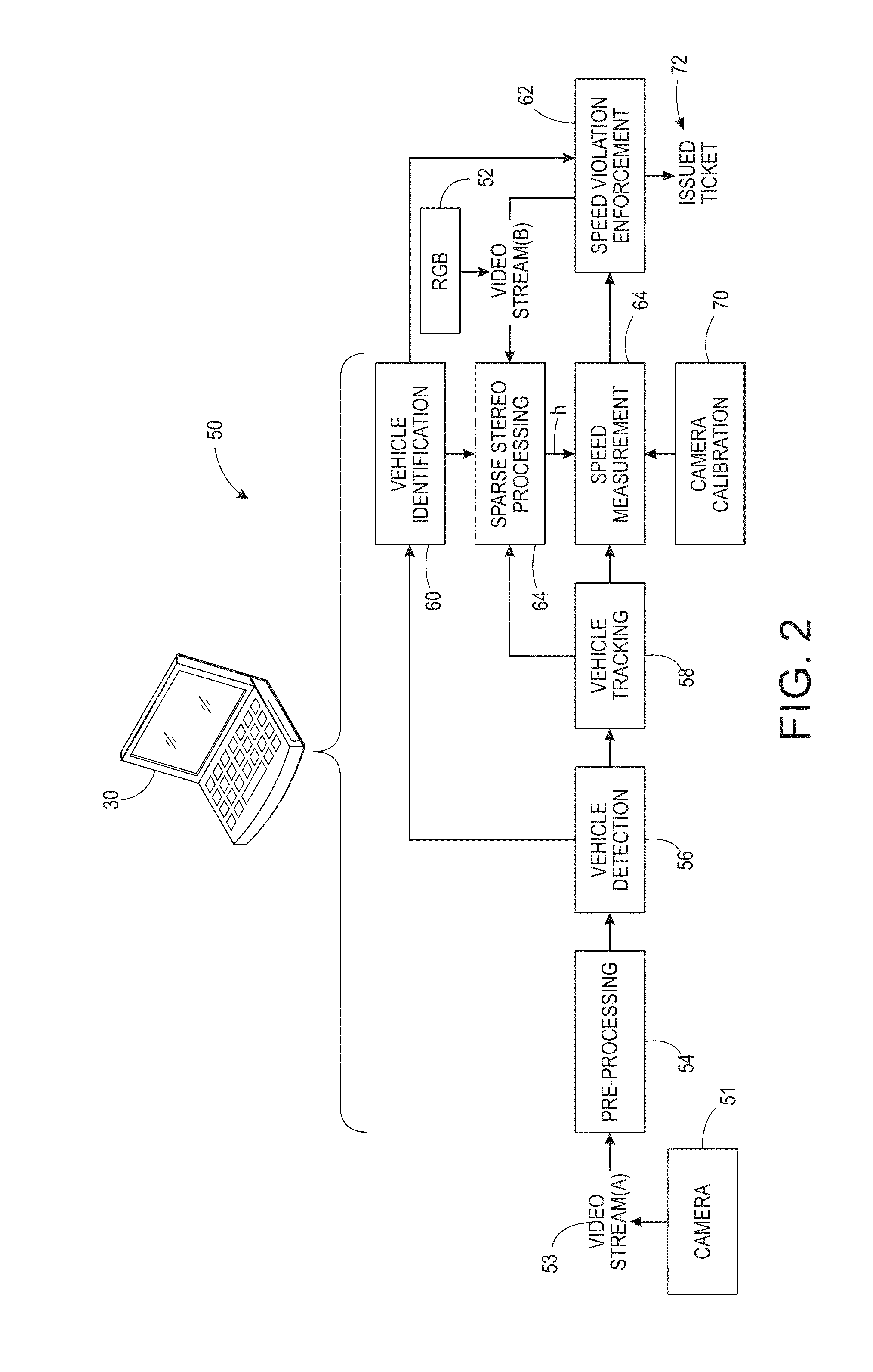
[0015]The above-described problem is solved by providing a video-based speed enforcement system that utilizes a main camera and a secondary traffic camera, such as a low-cost red-green-blue (RGB) camera. The described systems and methods provide improved accuracy of speed measurement and improved evidentiary photo quality compared to single camera approaches. The use of an RGB traffic camera mitigates the cost associated with a conventional stereo camera since the conventional approach requires two identical expensive primary cameras, rather than one primary and one low-cost secondary camera as proposed herein. There is also a greatly reduced computational requirement compared to conventional stereo video, which is a significant benefit in the transportation industry due to a need for real-time processing and high data rates. By using secondary video, spatio-temporally sparse stereo processing is enabled specifically for estimating the height of a vehicle feature above the road surf...


PUM


Abstract

When performing video-based speed enforcement a main camera and a secondary RGB traffic camera are employed to provide improved accuracy of speed measurement and improved evidentiary photo quality compared to single camera approaches. The RGB traffic camera provides sparse secondary video data at a lower cost than a conventional stereo camera. The sparse stereo processing is performed using the main camera data and the sparse RGB camera data to estimate a height of one or more tracked vehicle features, which in turn is used to improve speed estimate accuracy. By using secondary video, spatio-temporally sparse stereo processing is enabled specifically for estimating the height of a vehicle feature above the road surface.

Description

TECHNICAL FIELD[0001]The presently disclosed embodiments are directed toward video-based vehicular speed law enforcement. However, it is to be appreciated that the present exemplary embodiments are also amenable to other like applications.BACKGROUND[0002]Conventional single camera systems are hindered by limited abilities to accurately detect vehicle speed due to limitations associated with viewing a 3D world with 2D imaging devices. Additionally, the quality of evidentiary photos provided by such systems is unsatisfactory due to the retro-reflective properties of license plates, which requires a sensor operating at high dynamic range at night. Moreover, the camera field of view (FOV) conventionally is calibrated for speed detection accuracy, which conflicts with larger FOV requirements in traffic monitoring and incident detection. The performance of systems with such wide FOV in speed estimation tasks typically exhibits a large degree of estimation error unless additional elements ...

Claims


Application Information

Patent Timeline
Patent Type & Authority Patents(United States)
IPC IPC(8): H04N7/18G08G1/054G08G1/017
CPCG08G1/054G08G1/0175
Inventor WU, WENCHENGBERNAL, EDGAR A.LOCE, ROBERT P.WADE, THOMAS F.ISLAM, ABU
Owner CONDUENT BUSINESS SERVICES LLC
Learn More