
Ophthalmic lens with micro-acoustic elements

a technology of micro-acoustic elements and ophthalmic lenses, which is applied in the field of energized ophthalmic devices with micro-acoustic elements, can solve the problems of limited functionality and the increasing likelihood of creating wearable or embeddable micro-electronic devices, and achieve the effect of improving sound and improving performan

Active Publication Date: 2015-11-10
JOHNSON & JOHNSON VISION CARE INC
View PDF10 Cites 26 Cited by
  • Summary
  • Abstract
  • Description
  • Claims
  • Application Information

AI Technical Summary

Problems solved by technology

Moreover, as electronic devices continue to be miniaturized, it is becoming increasingly more likely to create wearable or embeddable microelectronic devices for a variety of uses.
However, these have been independent sound devices with limited functionality and typically include various mounting means, usually large and impractical, to allow for their use.

Method used


Image

  • Ophthalmic lens with micro-acoustic elements
  • Ophthalmic lens with micro-acoustic elements
  • Ophthalmic lens with micro-acoustic elements

Examples


Embodiment Construction

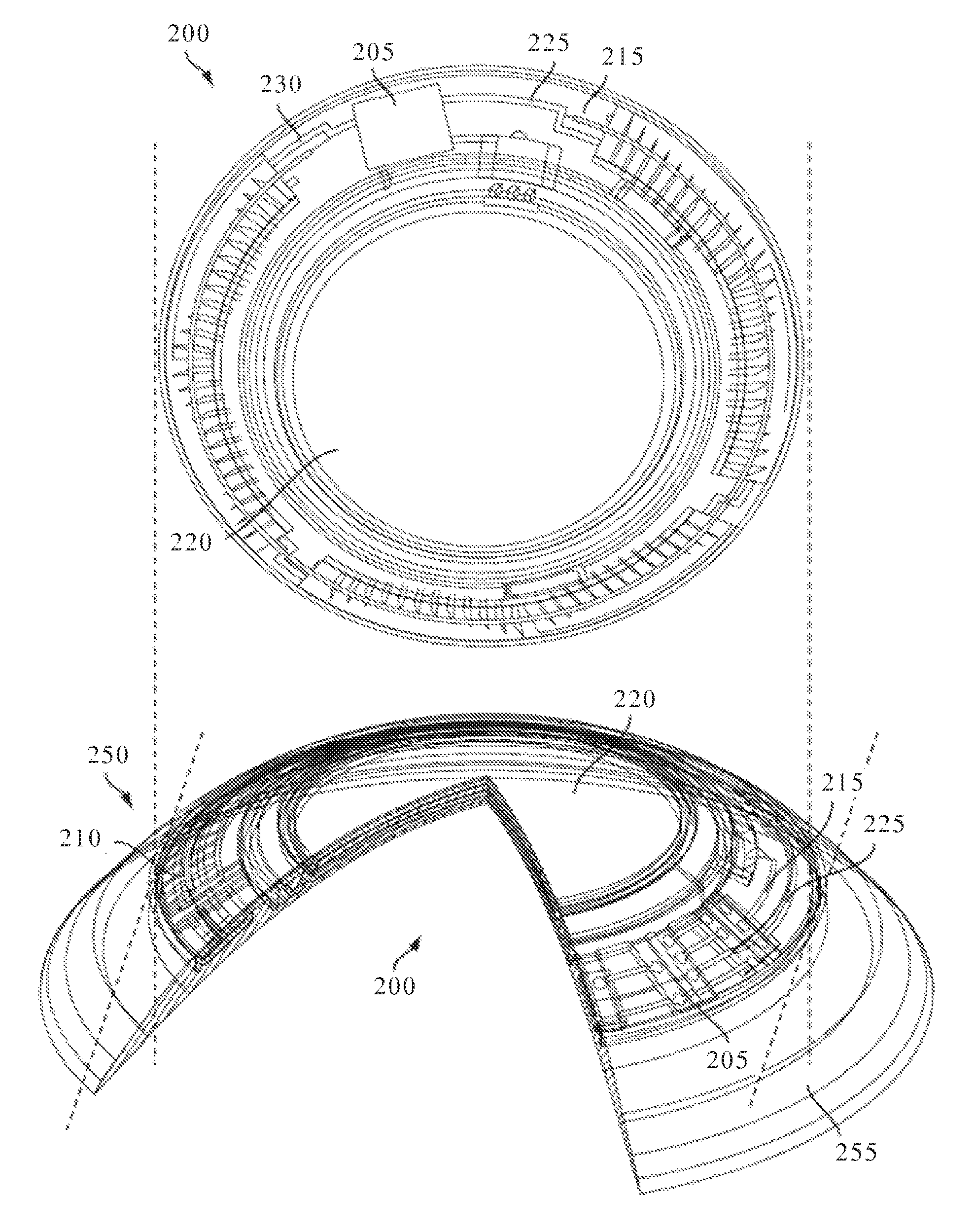
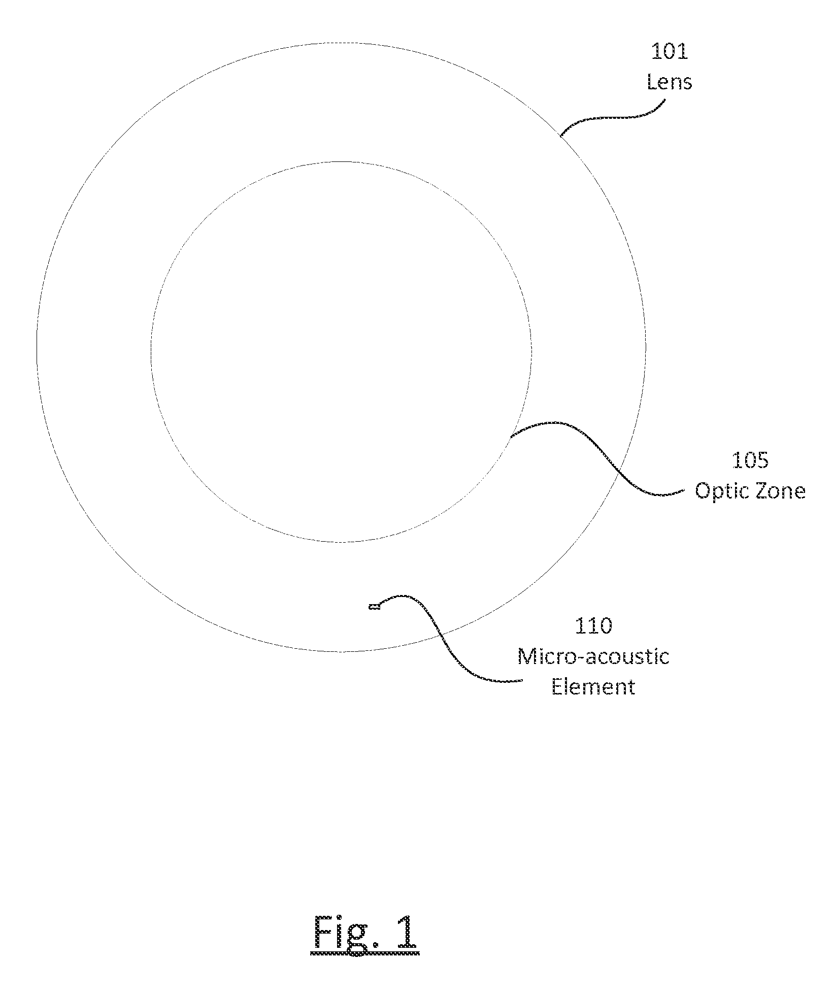
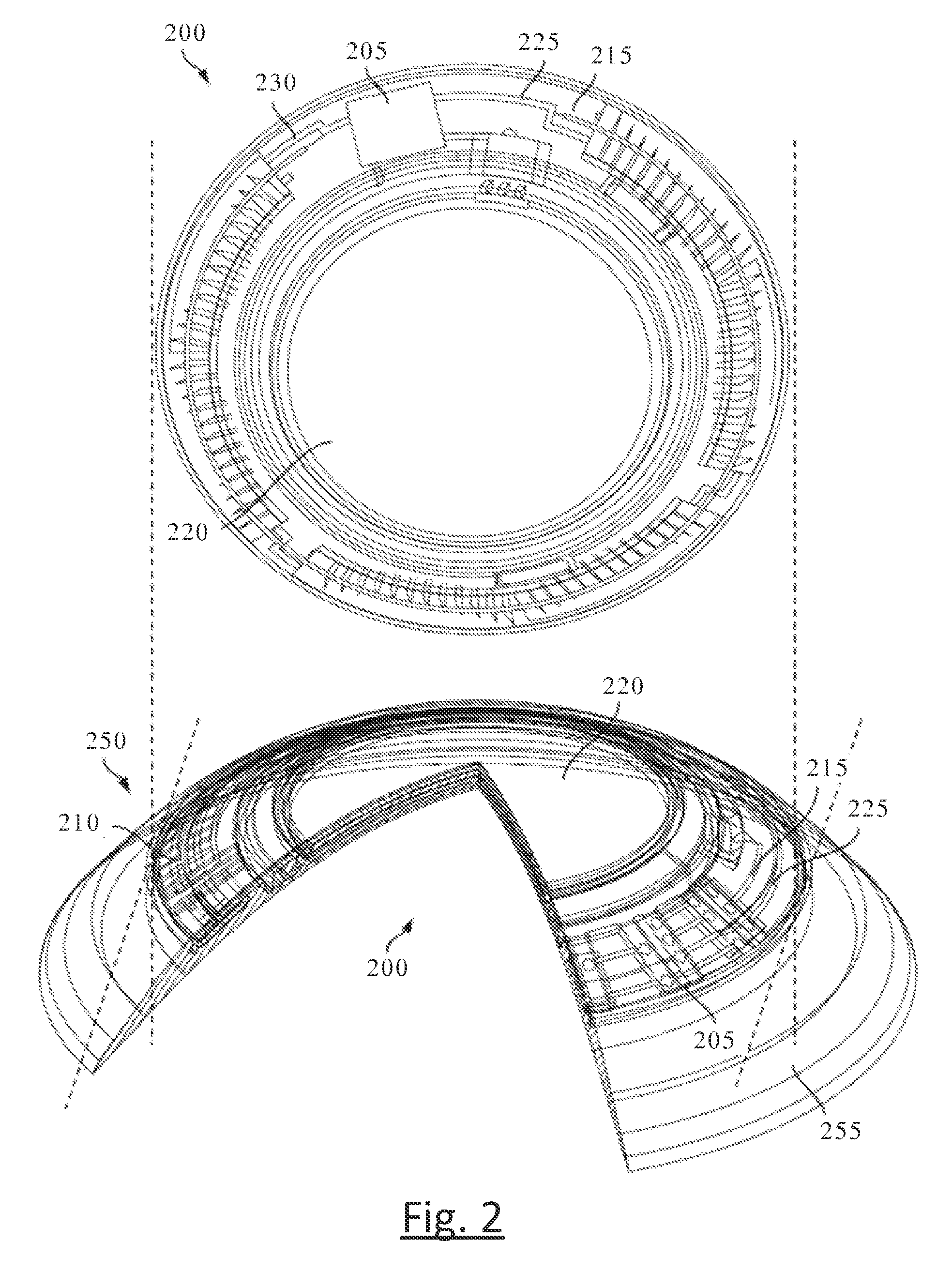
[0017]The disclosure will now be described with reference to the drawing figures, in which like reference numerals refer to like parts throughout.

[0018]Various aspects of the ophthalmic device and method disclosed may be illustrated by describing components that are coupled, sealed, attached, and / or joined together. As used herein, the terms “coupled”, “sealed”, “attached”, and / or “joined” are used to indicate either a direct connection between two components or, where appropriate, an indirect connection to one another through intervening or intermediate components. In contrast, when a component is referred to as being “directly coupled”, “directly sealed”, “directly attached”, and / or “directly joined” to another component, there are no intervening elements present.

[0019]Relative terms such as “lower” or “bottom” and “upper” or “top” may be used herein to describe one element's relationship to another element illustrated in the drawings. It will be understood that relative terms are...


PUM


Abstract

The present invention discloses an ophthalmic device with micro-acoustic electromechanical elements and associated methods. In some embodiments, the micro-acoustic electromechanical elements may be useful for the purpose of providing audible warnings and / or messages to a user. The audible warnings and / or messages can include, for example, messages transmitted wirelessly through a communication element of the ophthalmic device and / or generated within the ophthalmic device. In addition, in some embodiments the ophthalmic device can be an energized contact lens that is used both for optical correction and the transmission of sound through bone resonance to the inner ear of a user.

Description

FIELD OF THE INVENTION[0001]This invention describes an energized Ophthalmic Device with micro-acoustic elements, and more specifically, the micro-acoustic elements forming part of the Ophthalmic Device and being capable of transmitting sound through bone resonance to the inner ear.BACKGROUND OF THE INVENTION[0002]Traditionally, an ophthalmic device, such as a contact lens, an intraocular lens, or a punctal plug, included a biocompatible device with a corrective, cosmetic, or therapeutic quality. A contact lens, for example, may provide one or more of vision correcting functionality, cosmetic enhancement, and therapeutic effects. Each function is provided by a physical characteristic of the lens. A design incorporating a refractive quality into a lens may provide a vision corrective function. A pigment incorporated into the lens may provide a cosmetic enhancement. An active agent incorporated into a lens may provide a therapeutic functionality. Such physical characteristics are acco...

Claims


Application Information

Patent Timeline
Patent Type & Authority Patents(United States)
IPC IPC(8): H04R25/00G02C11/00A61F2/16H04R1/46G06F19/00G02C7/04
CPCH04R1/46A61F2/16G02C7/04G02C11/10G06F19/3418H04R25/606A61B5/7405A61B5/7455A61B5/002A61B5/14507A61B5/14532A61B5/6821A61B2010/0067A61B10/0045H04R17/00H04R2201/003G16H40/63
Inventor PUGH, RANDALL BRAXTON
Owner JOHNSON & JOHNSON VISION CARE INC
Learn More