Nanoelectronic-enzyme linked immunosorbent assay system and method

a technology of immunosorbent assay and nano-enzyme, which is applied in the field of nano-enzyme linked immunosorbent assay system and method, can solve the problems of poor sensing capability, unreliable product performance and consistency, and typical silicon-based nano-wire fabrication process exhibit relatively poor material and device service li

Active Publication Date: 2015-11-17
YALE UNIV
View PDF24 Cites 14 Cited by
  • Summary
  • Abstract
  • Description
  • Claims
  • Application Information

AI Technical Summary

Problems solved by technology

Although these, and other, silicon-based nano-sensors have been reported, they have exhibited poor sensing capabilities and their fabrication typically requires complex hybrid manufacturing methods having unreliable product performance and consistency.
In addition, typical silicon-based nano-wire fabrication processes exhibit relatively poor material and device service life, thereby further discouraging nano-wire sensor incorporation into larger integrated detector systems.

Method used


Image

  • Nanoelectronic-enzyme linked immunosorbent assay system and method
  • Nanoelectronic-enzyme linked immunosorbent assay system and method
  • Nanoelectronic-enzyme linked immunosorbent assay system and method

Examples


experimental examples

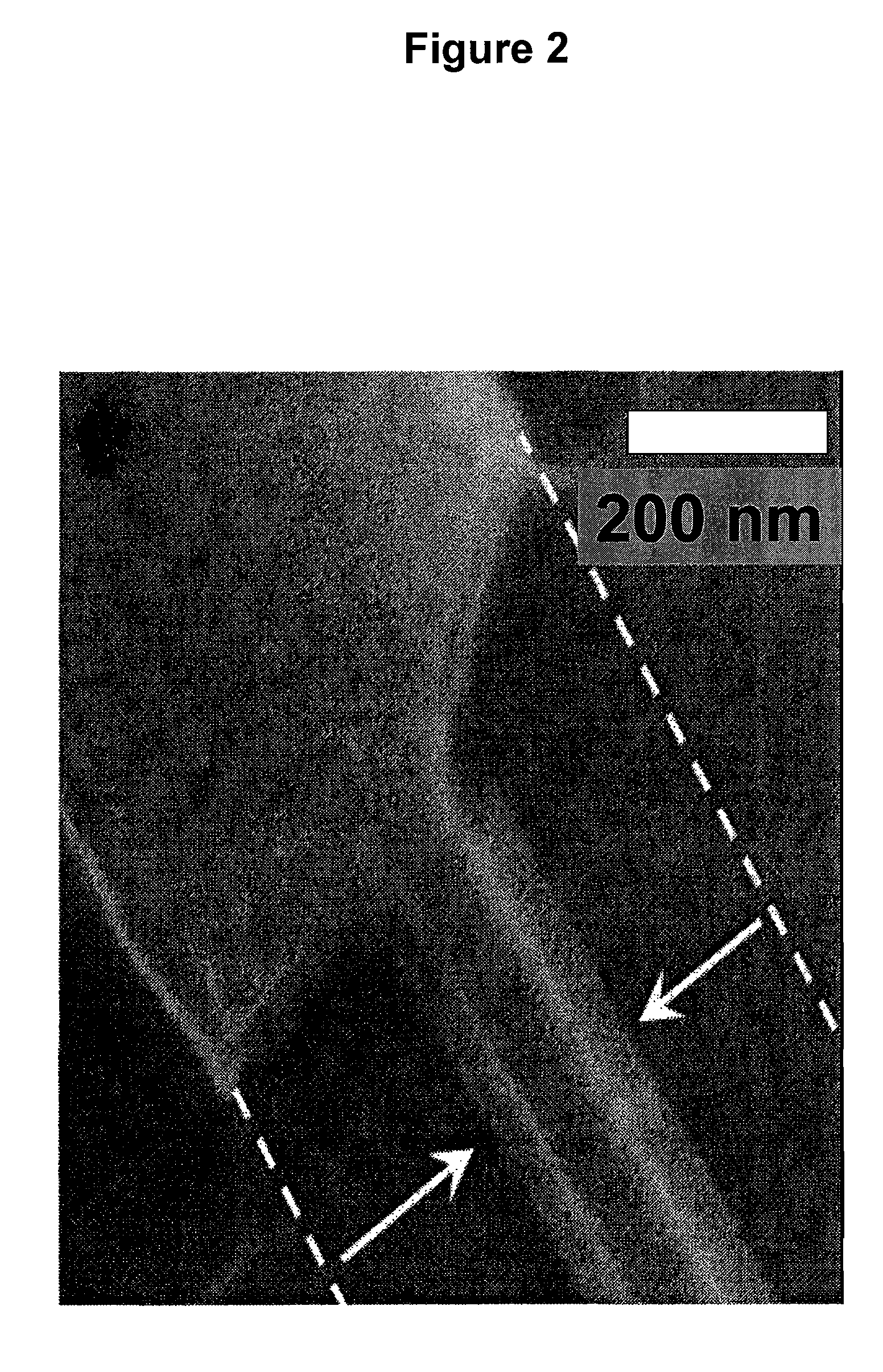
[0140]In one embodiment, indium oxide nanowires were used. These nanowires were grown by the laser-ablated hot-wall chemical vapor deposition method using a gold catalyst. Devices were fabricated on 2-inch wafers with a global backgate, and contacts to the nanowires were defined with a nickel / gold (Ni / Au) stack. After preliminary screening, wafers were diced and functionalized as shown in FIG. 21B. This scheme was designed to solely functionalize the gold leads due to thiol-mediated self-assembled monolayer (SAM) formation. Thus, surface hydroxyl groups on the indium oxide nanowires was maintained and available for protonation and deprotonation necessary for measuring solution pH. FIG. 22A is a scanning electron micrograph of a representative device, a ˜50-nm diameter nanowire between Ni / Au leads.

[0141]Samples were first treated with ω-mercaptocarboxylic acid (FIG. 21B-i) to confer carboxylic acid functionality to the gold leads. Gold leads contacting the nanowires were used for con...


PUM

PropertyMeasurementUnit
lengthaaaaaaaaaa
T cell response timeaaaaaaaaaa
pHaaaaaaaaaa

Abstract

The present invention relates to a device and method for determining the presence of a specific compound in solution. The device includes a nanosensor having an electrically conducting pathway between at least a first and second contact. The device also includes a first receptor, suitable for binding a specific compound in the solution, attached to the nanosensor, and a second receptor also suitable for binding the specific compound while the specific compound is bound to the first receptor. The second receptor is attached to an enzyme added to the solution. When the solution having the second receptor is added to the device, and a second compound that is a substrate for the enzyme is subsequently added to the solution, a measured difference in an electrical property in the device before and after the application of the second compound is indicative of the presence of the specific compound in the solution.

Description

CROSS-REFERENCE TO RELATED APPLICATIONS[0001]This application is a continuation-in-part of U.S. patent application Ser. No. 12 / 517,230, filed Jun. 2, 2009 now U.S. Pat. No. 9,076,665, which is a National Stage Application of PCT International Application No. PCT / US07 / 024,958, filed Dec. 6, 2007, which in turn claims the benefit of U.S. Provisional Application No. 60 / 873,070 filed on Dec. 6, 2006 and U.S. Provisional Application No. 60 / 873,740, filed on Dec. 8, 2006, each of which is incorporated by reference herein in its entirety.STATEMENT REGARDING FEDERALLY SPONSORED RESEARCH OR DEVELOPMENT[0002]This invention was made, in part, using funds obtained from the U.S. Government ARO, WF11NF-08-1-0365 and NIH RO1 (EB008260). The U.S. Government also has a paid-up license in this invention and the right in limited circumstances to require the patent owner to license others on reasonable terms as provided for by the terms of Contract Nos. ONR K00134, AFOSR L00084, and AFOSR R06868 and gr...

Claims


Application Information

Patent Timeline
Patent Type & Authority Patents(United States)
IPC IPC(8): G01N33/543G01N33/68
CPCG01N33/6866G01N33/54373G01N33/6863G01N33/6869G01N2333/54G01N2333/555G01N33/54366G01N2333/98
Inventor FAHMY, TAREK M.STERN, ERIC D.REED, MARK A.VACIC, ALEKSANDARKLEMIC, JAMES F.
Owner YALE UNIV
Why Eureka
Try Eureka