Porous conductive scaffolds containing battery materials

a technology of conductive scaffolds and batteries, applied in the field of improved batteries, can solve the problems of multiple challenges of implementation of nanometer-sized battery materials, slow ion diffusion, and lower power output, and achieve the effect of reducing the sintering of oxide materials

Inactive Publication Date: 2014-12-30
HRL LAB
View PDF8 Cites 10 Cited by
  • Summary
  • Abstract
  • Description
  • Claims
  • Application Information

AI Technical Summary

Benefits of technology

[0009]Preferably, the scaffold material is substantially stable under battery reaction conditions. The pres...

Problems solved by technology

Nanometer-sized battery materials have multiple challenges for implementation, however.
Bulk structures have relatively long diffusion distances which results in slower ion diffusion during battery operation, and thus lower power output.
Additionally, bulk structures can readily lose electrical contact with the electrode due to stress cracking as ions diffuse into and out of them, thereby reducing battery capacity.
Also, it is difficult to form electrical connections to n...

Method used


Image

  • Porous conductive scaffolds containing battery materials
  • Porous conductive scaffolds containing battery materials
  • Porous conductive scaffolds containing battery materials

Examples


example 1

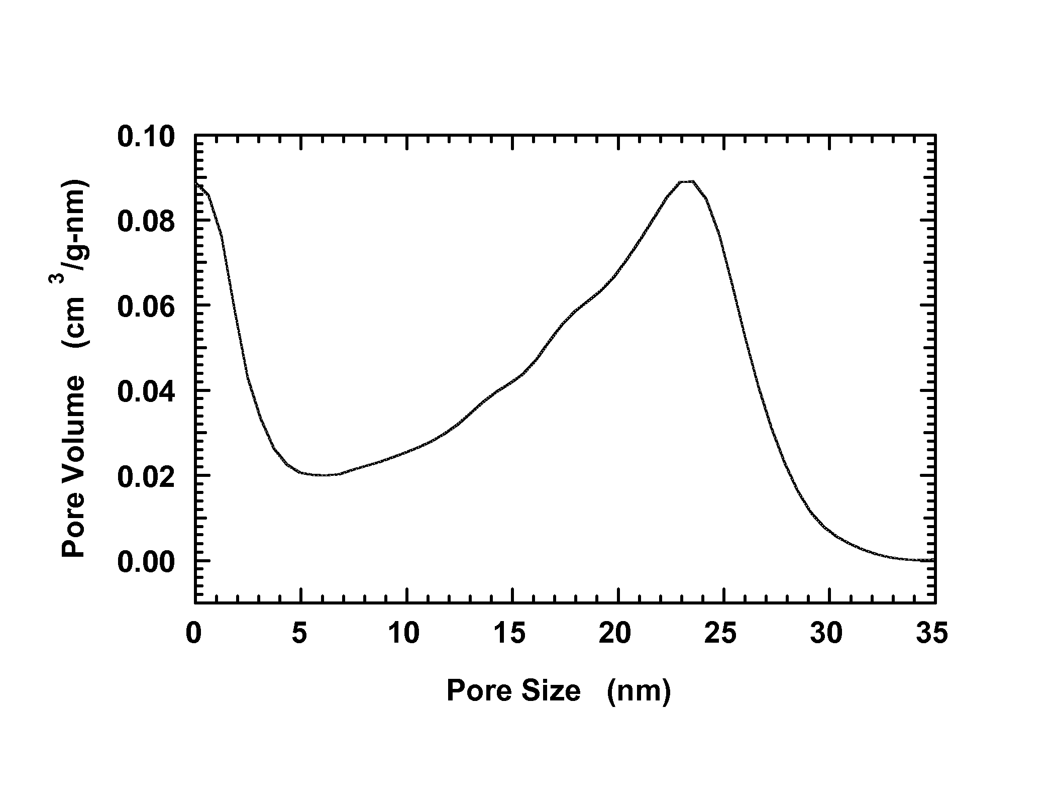
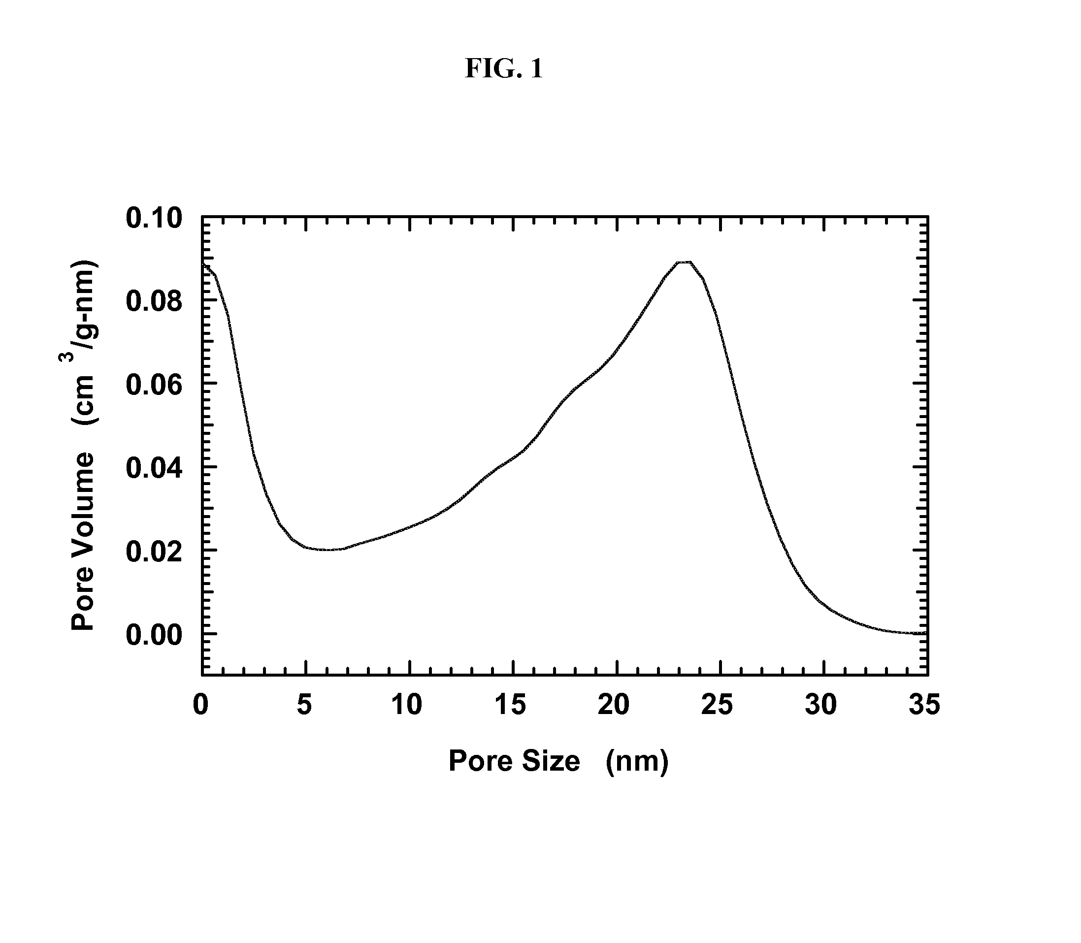
[0055]A carbon aerogel with a peak in the pore-size distribution at 25 nm is produced using resorcinol-formaldehyde condensation as partially described in Li et al., Chem. Mater. 2004, 16, 5676, which is hereby incorporated by reference herein to the extent there is no conflict with this specification.

[0056]First 20.70 g (188 mmol) resorcinol (Aldrich), 30.94 g of 36.5 wt % formaldehyde solution in water (376 mmol formaldehyde, Fluka), and 28.32 g deionized water are mixed until all materials are in solution. Then sodium carbonate (0.040 g, 0.377 mmol) is added and the mixture is stirred until dissolved. The solution is transferred in equal amounts to three 60-mL polypropylene jars, sealed, and aged 24 hrs at 23° C., 24 hrs at 50° C., and then 72 hrs at 90° C. The samples are then cooled, cut into cubes (0.75 cm / side), and immersed in acetone to displace the water. The acetone bath is poured off and refilled twice with at least one hour between cycles. The aerogel cubes are allowed ...

example 2

[0058]Iron oxide-filled aerogels are produced by melting a hydrate of iron nitrate into the carbon aerogel described in Example 1 herein. 1.30 g of carbon aerogel as provided in Example 1 is evacuated and heated to 400° C. under vacuum for one hour to remove residual water from the pores. The flask containing the aerogel is cooled and backfilled with argon. Then 5 g of iron nitrate hydrate, Fe(NO3)3.9H2O, is melted by heating to 60° C. The aerogel is placed in the molten iron nitrate and agitated for 10 min. The aerogel cubes are removed from the iron nitrate nonahydrate and placed in a glass beaker. The cubes are heated in air at 2° C. / min to 150° C., are held at 150° C. for 8 hours, and then are cooled. Next the aerogel cubes are heated under argon at 2° C. / min to 350° C., are held at 350° C. for 3 hours, and then are cooled.

[0059]To measure the iron oxide loading, thermogravimetric analysis (TGA) is performed using a TA 2950 analyzer (TA Instruments). The samples are heated at a ...

example 3

[0062]Cobalt oxide-filled aerogels are produced by melting a hydrate of cobalt nitrate into a carbon aerogel provided in Example 1. 1.26 g of this carbon aerogel is evacuated and heated to 400° C. under vacuum for one hour to remove residual water from the pores. The flask containing the aerogel is cooled and backfilled with argon. Then 5 g of Co(NO3)2.6H2O is melted by heating to 70° C. The aerogel is placed in the molten cobalt nitrate hexahydrate and agitated for 10 min until it has absorbed as much cobalt nitrate hydrate as possible. Then the aerogel cubes are removed from the liquid and placed in a glass beaker. The cubes are heated in air at 2° C. / min to 150° C., are held at 150° C. for 8 hours, and then are cooled. Next the aerogel cubes are heated under argon at 2° C. / min to 350° C., are held at 350° C. for 3 hours, and then are cooled.

[0063]To measure the cobalt oxide loading, TGA is performed using a TA 2950 analyzer (TA Instruments). The samples are heated at a ramp rate ...


PUM


Abstract

The present invention provides a battery electrode comprising an active battery material enclosed in the pores of a conductive nanoporous scaffold. The pores in the scaffold constrain the dimensions for the active battery material and inhibit sintering, which results in better cycling stability, longer battery lifetime, and greater power through less agglomeration. Additionally, the scaffold forms electrically conducting pathways to the active battery nanoparticles that are dispersed. In some variations, a battery electrode of the invention includes an electrically conductive scaffold material with pores having at least one length dimension selected from about 0.5 nm to about 100 nm, and an oxide material contained within the pores, wherein the oxide material is electrochemically active.

Description

FIELD OF THE INVENTION[0001]The present invention generally relates to improved batteries, and methods of making such batteries.BACKGROUND OF THE INVENTION[0002]Batteries based on lithium (Li), such as lithium-ion batteries, are attractive due to their high energy density compared to other commercial batteries (e.g., alkaline batteries). Li-ion batteries are used commercially in computers, cell phones, and related devices. Li-ion batteries have potential for use in electric vehicle and hybrid-electric vehicle applications.[0003]It is desirable to maintain high battery capacity while being electrochemically reversible. Appropriate nanomaterials enable fast reaction kinetics due to reduced diffusion distances. Higher power output and faster charging times can result when lithium ions are able to diffuse into and out of the active battery material quickly. Nanometer-sized battery materials have multiple challenges for implementation, however.[0004]When batteries are cycled through char...

Claims


Application Information

Patent Timeline
IPC IPC(8): H01M4/66
CPCH01M4/66H01M4/485H01M4/505H01M4/525H01M4/624H01M4/625Y10S977/78Y10S977/948Y02E60/10Y02P70/50B82Y30/00H01M4/04H01M4/48H01M4/502H01M4/523H01M4/663H01M10/0525H01M10/058H01M2220/20
Inventor GROSS, ADAM F.VAJO, JOHN J.LIU, PINGSHERMAN, ELENA
Owner HRL LAB
Why Eureka
Try Eureka