Time-of-flight imager
a technology of time-of-flight and imager, which is applied in the direction of electromagnetic wave reradiation, measurement devices, instruments, etc., can solve the problems of pulse propagation delay across the array, insatiable depth maps, etc., and achieve the effect of improving accuracy
- Summary
- Abstract
- Description
- Claims
- Application Information
AI Technical Summary
Benefits of technology
Problems solved by technology
Method used
Image
Examples
Embodiment Construction
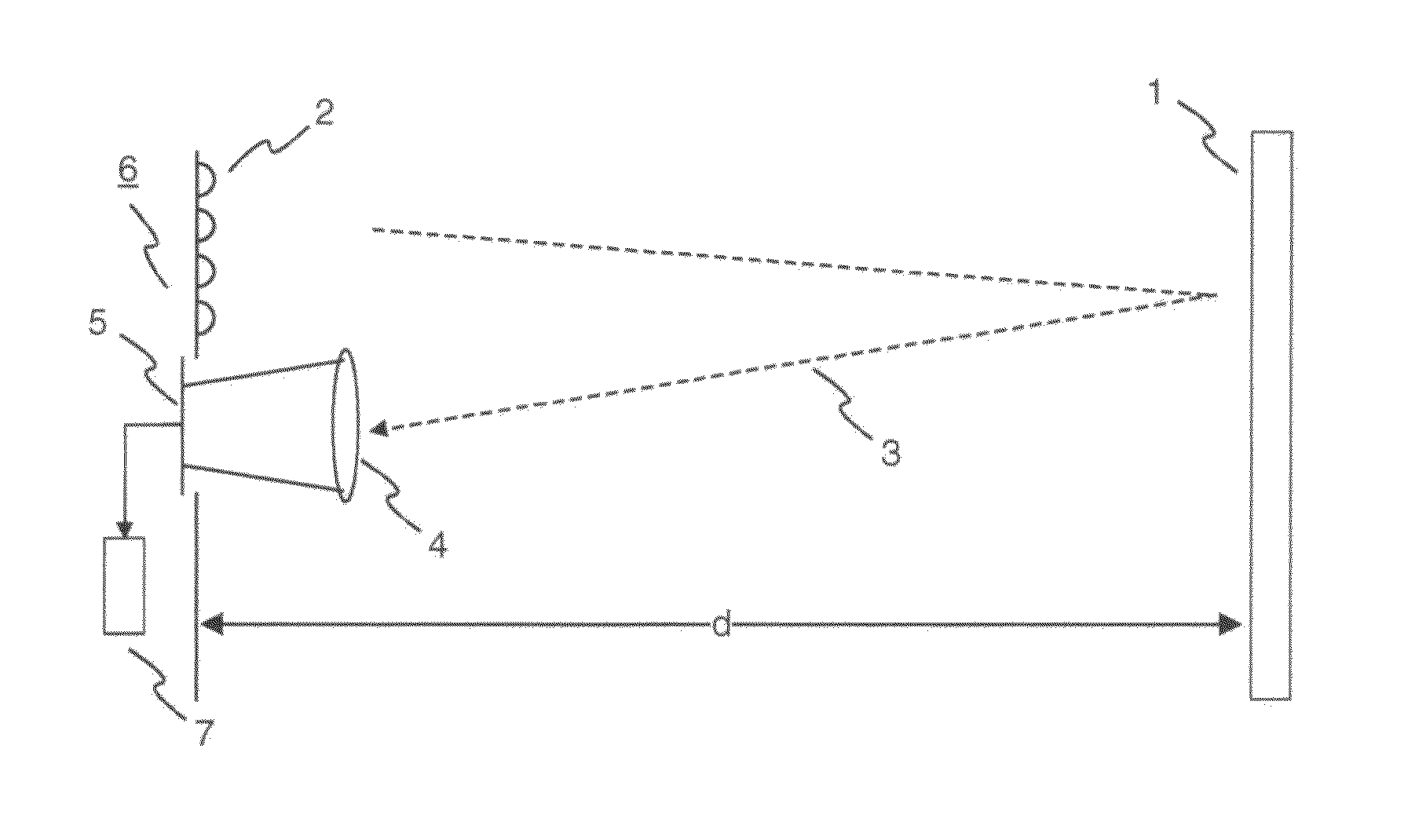
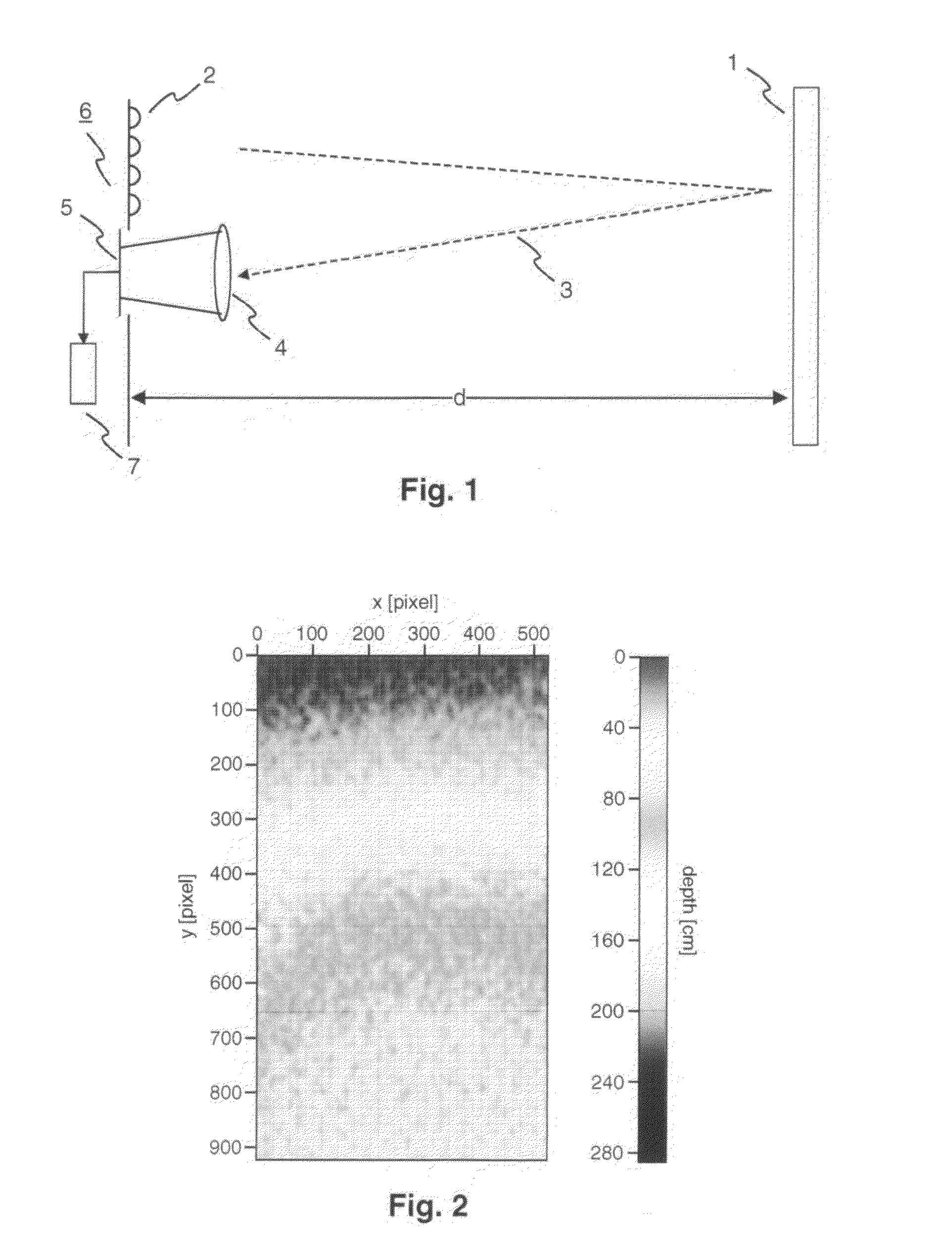
[0041]FIG. 1 illustrates the principle of a time-of-flight imager 6 according to the invention. The time-of-flight imager 6 includes a light source 2, a lens 4, a sensor 5, and processing circuitry 7. An object 1 located at a distance d of 75 cm from the time-of-flight imager 6 is illuminated by the light source 2, e.g. a 4×4 array of infrared LEDs. The object 1 has a flat surface facing an array of pixels of the sensor 5. The light 3 reflected by this flat surface is collected by the lens 4 and imaged onto the array of pixels of sensor 5. This allows to measure a depth map of the object 1. The processing circuitry 7 enables processing of the measured depth map.
[0042]The depth map of the object 1 measured by the time-of-flight imager 6 is shown in FIG. 2. The grey values indicate the measured depth in cm. They are plotted against the pixels of the sensor 5 in x- and y-direction. Though the flat surface of the object 1 has a fixed distance d of 75 cm from the plane of the sensor 5, t...
PUM
 Abstract
Description
Claims
Application Information
 - R&D
- Intellectual Property
- Life Sciences
- Materials
- Tech Scout
- Unparalleled Data Quality
- Higher Quality Content
- 60% Fewer Hallucinations
Browse by: Latest US Patents, China's latest patents, Technical Efficacy Thesaurus, Application Domain, Technology Topic, Popular Technical Reports.
© 2025 PatSnap. All rights reserved.Legal|Privacy policy|Modern Slavery Act Transparency Statement|Sitemap|About US| Contact US: help@patsnap.com


