Vibration exciter for generating a directed excitation vibration

a vibration exciter and excitation technology, applied in the direction of belts/chains/gears, mechanical equipment, gearing, etc., can solve the problem of lack of effective vector adjustment, and achieve the effect of cost-effectiveness

Active Publication Date: 2015-11-24
BOMAG
View PDF32 Cites 7 Cited by
  • Summary
  • Abstract
  • Description
  • Claims
  • Application Information

AI Technical Summary

Benefits of technology

[0011]The present invention is consequently based on the object of further developing a vibration exciter for generating a directed excitation vibration of the kind mentioned above in such a way that a reliable amplitude adjustment and vector adjustment of the excitation vibration is ensured in combination with a sturdy and cost-effective configuration.
[0016]It is further advantageous in the aforementioned central adjusting element to arrange its configuration in such a way that the vibration exciter can be rotatably positioned about the central adjusting element for the purpose of vector adjustment of the vibration amplitude or the excitation force. The central adjusting element therefore preferably acts not only as an adjusting element for the amplitude adjustment but also as a rotational axis or bearing for the vector adjustment. For the purpose of vector adjustment, the vibration exciter can rotate about the central adjusting element or a bearing element arranged in a respectively coaxial manner in relation to the central adjusting element (especially by 90°), so that the direction of the vibration amplitude will change. As a result, the vector adjustment can be used among other things to change a compaction amplitude directed orthogonally to the ground surface into a compaction amplitude acting horizontally in relation to the ground surface.
[0017]The rotational axis of the vector adjustment preferably extends coaxially with the main extension axis of the adjusting element, wherein the central adjusting element can also be arranged itself as a bearing axis or as a guide axis for a bearing, etc. As a result of the arrangement of the adjusting element coaxially to the rotational axis of the vector adjustment, a highly compact vibration exciter is obtained which is optimized with respect to the loads to be carried off. This advantage will be further amplified by arranging the central adjusting element as a rotational axis or as a bearing for such an axis itself.
[0018]Preferably, the central adjusting element is in operative connection with a first and second axial adjusting element via a yoke element, which axial adjusting elements extend in parallel to the two unbalance shafts and are in a spiral-groove driving engagement with the movable unbalance masses of the unbalance shafts in such a way that an axial movement of the central adjusting element causes a rotational motion of the movable unbalance masses about the respective unbalance shaft and therefore the amplitude adjustment. It is especially the arrangement of a central adjusting element which is in connection with the two axial adjusting elements via a yoke element that guarantees the compact and load-optimized arrangement of a vibration exciter. The yoke element is preferably arranged in such a way that it can dissipate both the axially acting adjusting forces for amplitude adjustment and also the tangentially acting rotational forces in vector adjustment.
[0020]Optimal bearing of the vibration exciter on or in a machine, and especially in a vibration tamper, is ensured when the central adjusting element comprises at least one rotational bearing element or is in operative connection with the same, by means of which the vibration exciter can be arranged on at least one external fixed point on the machine. As a result, the vibration exciter can be rotated relative to the machine for the vector adjustment about the central adjusting element or about its main extension axis.
[0024]The rotational force element and the axial force element can further be arranged on one side of the vibration exciter and especially on one side of the central adjusting element. This enables a compact and cost-effective configuration.

Problems solved by technology

The disadvantage of the vibration exciters known from the state of the art lies on the one hand in the complex configuration of an adjusting device for the adjustment of the movable unbalance masses on the two unbalance shafts, and on the other hand in the lack of an effective vector adjustment and the possibility to enable such a vector adjustment in a simple and technically reliable manner.

Method used


Image

  • Vibration exciter for generating a directed excitation vibration
  • Vibration exciter for generating a directed excitation vibration
  • Vibration exciter for generating a directed excitation vibration

Examples


Embodiment Construction

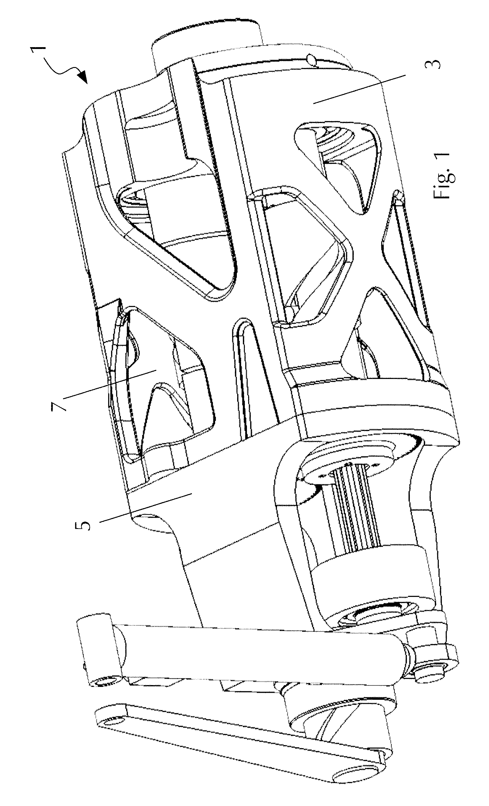
[0042]FIG. 1 shows an isometric view of an embodiment of the vibration exciter 1 in accordance with the present invention.

[0043]The vibration exciter 1 comprises an exciter housing 3 with a housing head 5 forming a receiving space for excitation means 7 which allow producing a directed excitation vibration. The illustrated vibration exciter can be installed in a construction machine such as a vibration tamper as shown in FIG. 10.

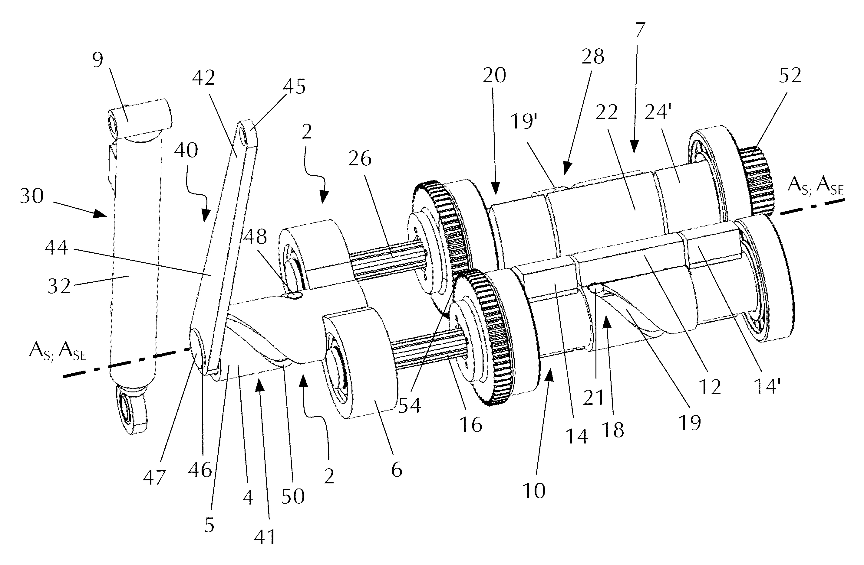
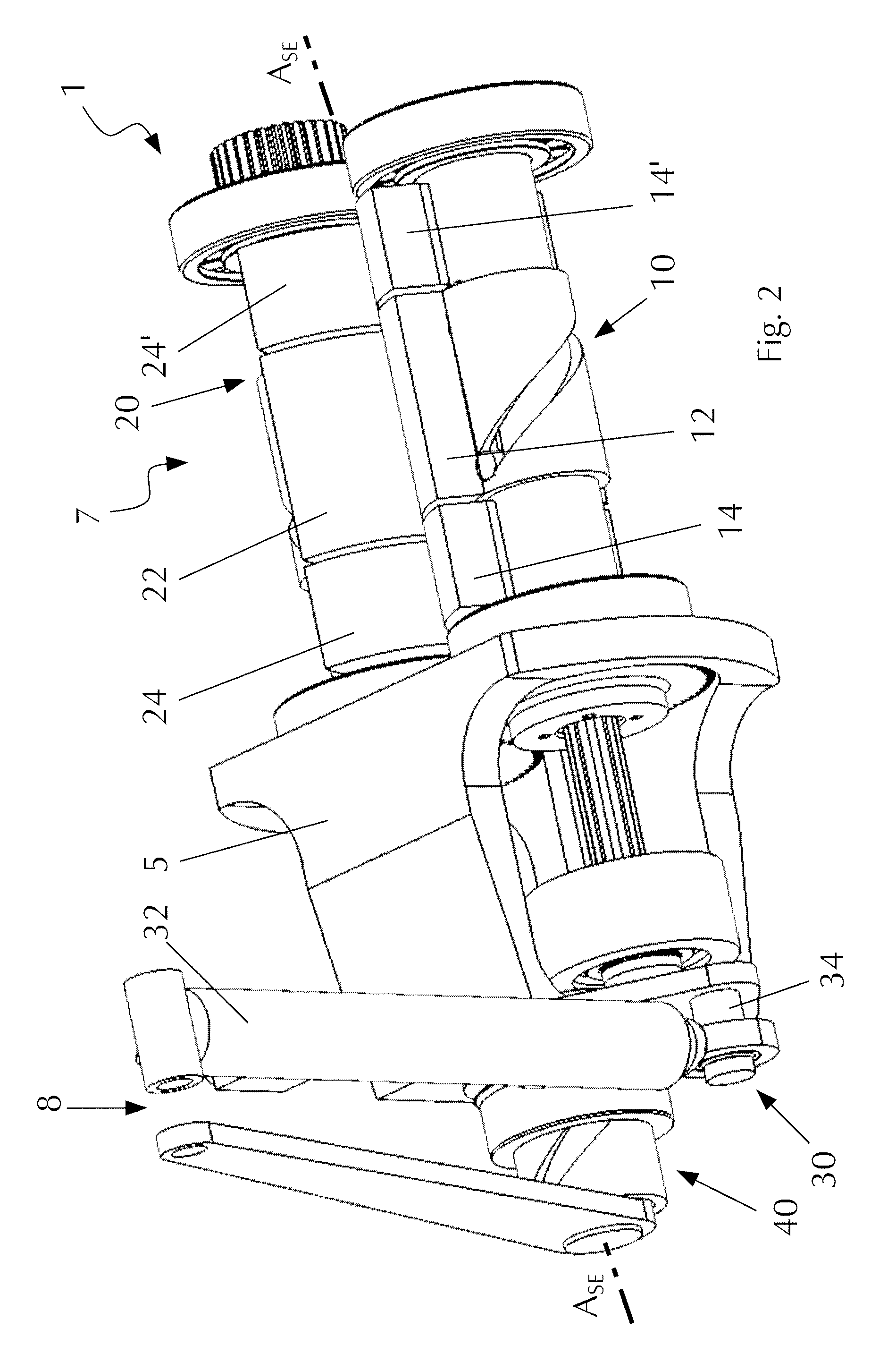
[0044]FIG. 2 shows the embodiment according to FIG. 1, with the exciter housing having been partly removed so that the excitation means 7 are now clearly to be seen. The excitation means 7 concern two unbalance shafts 10, 20, on which both movable unbalance masses 12, 22 and also fixed unbalance masses 14, 24 are arranged.

[0045]The unbalance masses 12, 22 are movable via an adjusting device 2 comprising an axial force element 40 relative to the fixed unbalance masses 14, 24 and especially rotatable about the respective unbalance shaft 10, 20 in such a way th...


PUM


Abstract

The present invention relates to a vibration exciter for generating a directed excitation vibration, especially for installation in a vibration tamper, and a machine with such a vibration exciter, comprising at least two parallel extending unbalance shafts which are rotatable against one another, on which at least one respective fixed unbalance mass and at least one respective movable unbalance mass are arranged, with the positions of the movable unbalance masses on the unbalance shafts being variable by way of an adjusting device for adjusting the amplitude of the exciter vibration, and with the adjusting device comprising a central adjusting element for amplitude adjustment which acts on the movable unbalance masses of the two unbalance shafts, which central adjusting element is arranged coaxially to a rotational axis (AS) about which the vibration exciter is rotatable for the purpose of vector adjustment of the excitation vibration.

Description

CROSS-REFERENCE TO RELATED APPLICATIONS[0001]The present application claims priority under 35 U.S.C. §119 of German Patent Application No. 10 2011 112 316.8, filed Sep. 2, 2011, the disclosure of which is hereby incorporated herein by reference in its entirety.FIELD OF THE INVENTION[0002]The present invention relates to a vibration exciter for generating a directed excitation vibration, especially for installation in a vibration tamper, comprising two unbalance shafts which extend in parallel and are rotatable against one another, on which at least one respective fixed unbalance mass and at least one respective movable unbalance mass are arranged, with the angular positions of the movable unbalance masses on the unbalance shafts being variable by way of an adjusting device for adjusting the amplitude of the exciter vibration.[0003]Furthermore, the present invention relates to a machine and especially a construction machine such as a vibration tamper with a vibration exciter of the k...

Claims


Application Information

Patent Timeline
Patent Type & Authority Patents(United States)
IPC IPC(8): B06B1/16
CPCB06B1/166Y10T74/18552
Inventor SCHMIDT, CHRISTIANWAGNER, JENS
Owner BOMAG
Why Eureka
Try Eureka