Pneumatic spring device for a motor vehicle

Active Publication Date: 2015-11-24
AUDI AG
View PDF27 Cites 10 Cited by
  • Summary
  • Abstract
  • Description
  • Claims
  • Application Information

AI Technical Summary

Benefits of technology

[0006]Object of the invention is to further refine a generic pneumatic spring dev

Problems solved by technology

Such a pneumatic spring is disadvantageous because it normally exhibits a firm behavior of the spring characteristic at small amplitudes of greater excitation frequency.
This tors

Method used


Image

  • Pneumatic spring device for a motor vehicle
  • Pneumatic spring device for a motor vehicle

Examples


Example

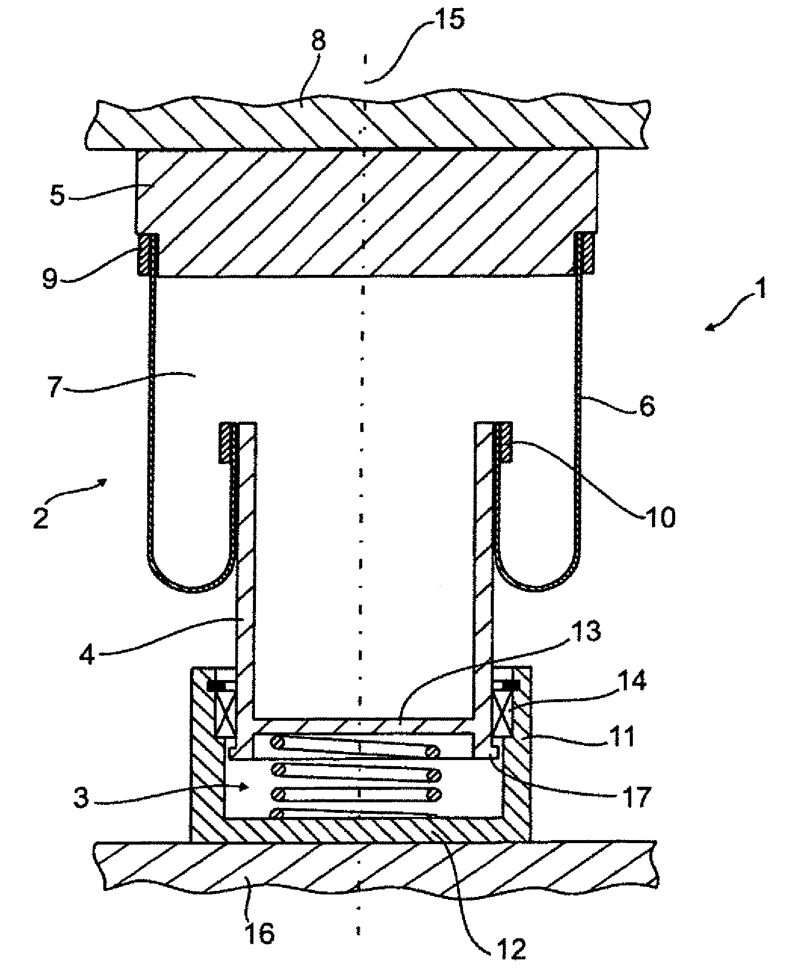
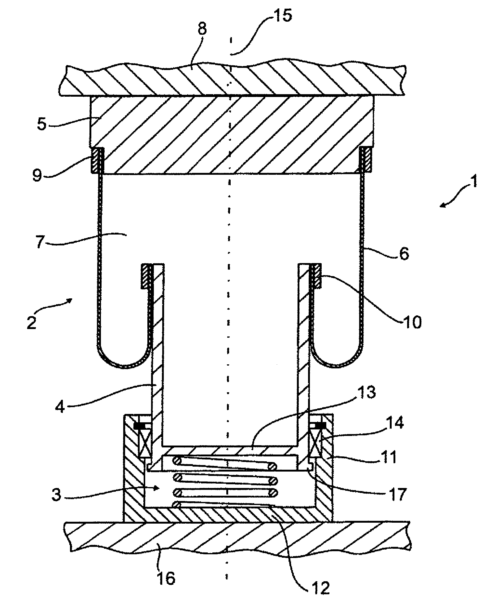
[0015]The pneumatic spring 2 includes a rolling piston 4, a pneumatic spring cover 5 movable in axial relation thereto, and an interposed rolling bellows 6 with a trapped compressible air volume 7. The pneumatic spring cover 5 is connected here to a (schematically shown) body structure 8.

[0016]The rolling bellows 6 is configured as transverse bellows, and has an upper end connected by a cover clamp 9 to the pneumatic spring cover 5 about its circumference. The lower end of the rolling bellows 6 is connected accordingly to the upper rolling piston end by a piston clamp 10.

[0017]The lower region of the rolling piston 4 is received in a cylindrical bearing cup 11 for axial movement and axially supported by the helical spring 3 between the bearing cup bottom 12 and the rolling piston bottom 13. In addition, the rolling piston 4 is radially held and supported by a radial bearing 14 arranged on the inner wall of the bearing cup. The radial bearing 14 is constructed as a sliding bearing so...


PUM


Abstract

The invention relates to a pneumatic spring device for a motor vehicle, including a rolling piston (4), a pneumatic spring cover (5) axially movable thereto, and an interposed elastomer covering as rolling bellows (6) with a trapped compressible air volume. According to the invention, at least one additional spring element (3) is connected in series to the pneumatic spring (2), with a radial bearing (14) of the rolling piston (4) and/or the pneumatic spring cover (5) being integrated as torsion compensation.

Description

CROSS-REFERENCES TO RELATED APPLICATIONS[0001]This application is the U.S, National Stage of International Application No. PCT / EP2012 / 003201, filed Jul. 27, 2012, which designated the United States and has been published as International Publication No. WO 2013 / 029725 and which claims the priority of German Patent Application, Serial No. 10 2011 112 130.0, filed Sep. 1, 2011, pursuant to 35 U.S.C. 119(a)-(d).BACKGROUND OF THE INVENTION[0002]The invention relates to a pneumatic spring device for a motor vehicle.[0003]A generic pneumatic spring device includes a generally known pneumatic spring which includes a rolling piston, a pneumatic spring cover which is moveable in axial relation to the rolling piston, and an interposed elastomer bellows configured as a rolling bellows with trapped compressible air volume. The spring action of such a pneumatic spring is based on the compression of air in the trapped air volume, with the air volume decreasing during spring compression as the rol...

Claims


Application Information

Patent Timeline
IPC IPC(8): B60G11/32B60G11/56F16F15/04F16F9/05B60G11/62F16F13/00
CPCB60G11/56B60G11/62F16F9/05F16F13/002F16F15/046F16F2230/0052
Inventor WILLEMS, MARCO
Owner AUDI AG
Why Eureka
Try Eureka