Method for controlling a network system, network system, and computer program

a network system and computer program technology, applied in the direction of digital computers, connection management, instruments, etc., can solve the problems that the network system of the office wlan system does not support the network having clients at all, and achieve the effect of optimizing the cycle time, facilitating application-based coordination, and efficiently using information

Active Publication Date: 2015-11-24
PHOENIX CONTACT GMBH & CO KG
View PDF14 Cites 0 Cited by
  • Summary
  • Abstract
  • Description
  • Claims
  • Application Information

AI Technical Summary

Benefits of technology

[0021]Another advantage of the invention is seen in customary WLAN infrastructures, in which a load distribution of clients on multiple access points is provided only via the configuration of the access points. The access points then decide whether other clients are permitted to log on to the wireless network, or how so-called Quality of Service (QoS) parameters are allocated for the WLAN communication. However, in this regard the access points have only limited knowledge concerning the actual application, i.e., which specific devices, for example cameras, input / output stations, or drive devices, are controlled. In this case the invention allows client-based load distribution (load balancing) by the fact that the clients centrally transmit status information to the client control device, which in this respect is more efficient because the clients are the actual load originators. In addition, the central coordination and control of the clients via the client control device allows significantly more application-based coordination of all users of the wireless network, in particular WLAN users, which in industrial applications such as materials handling technology, for example, is able to accept a much larger number of uniform device types.
[0022]The invention also allows interruption-free roaming, since the client control device is able to control the client in such a way that handover times of a client as the result of a new search for more accessible access points as well as authentication and association with an access point are avoided. Based on the knowledge of the client control device about the wireless network infrastructure, the client control device is able to send appropriate control signals to the client. The client control device in particular requires knowledge about the wireless network infrastructure based on the status information transmitted by the client and / or based on data transmitted to the client control device using a control device for wireless networks, for example a WLAN controller.
[0023]In one advantageous embodiment, it may be provided that the client control device transmits Ethernet telegrams and / or Ethernet packets between the client and the backbone network via the tunnel. In particular, the client control device bridges Ethernet telegrams and / or Ethernet packets from the clients and / or from the Ethernet users connected to the clients into the backbone network on ISO layer 2. The client control device preferably delivers telegrams, in particular Ethernet telegrams, from the backbone network via the tunnel to the clients and / or to the Ethernet users connected to the clients. The individual tunnel end points correspond to logically viewed bridge ports of a switch. Logically viewed, the client control device represents a switch having the tunnel end points as switch ports; in contrast to a customary switch, the client control device is able to resolve so-called loops, i.e., the particular clients that are linked to one another for roaming or redundancy reasons, for example, in particular on the Ethernet level, i.e., on the layer 2 level, and to efficiently use the information thus obtained for controlling the clients.
[0024]In another preferred embodiment of the invention, it may be provided that the data to be transmitted between the client control device and the client are transmitted cyclically. A cycle time may preferably be set using the client control device. However, it may also be provided that the cycle time is specified manually.
[0025]In another preferred embodiment of the invention, the client control device automatically optimizes the cycle time, in particular by taking into account the instantaneously available bandwidth of the wireless connection to the client. In another example of the embodiment of the invention, it may be provided that the cycle time is fixed via an automation application, for example the Profinet, wherein the client control device in particular adjusts a transmitting power or a roaming threshold in the client for ensuring the cycle time during operation.
[0026]According to another preferred embodiment of the invention, the data to be transmitted may be packed into a data frame. Such packing of data into a data frame is also referred to as packet aggregation. The data frame into which the data to be transmitted are packed may also be referred to as a tunnel frame. In particular, multiple Ethernet packets are packed into a data frame. Thus, multiple data items, in particular Ethernet packets, may be jointly transferred. By means of the packet aggregation according to the invention, low “jitter” is achieved in the communication between the client control device and the client and / or an Ethernet user or end user connected to the client, in particular when the data to be transmitted are transmitted cyclically between the client control device and the client, i.e., when the tunnel between the client control device and the client operates cyclically.

Problems solved by technology

A further disadvantage is that customary office WLAN systems provide no support at all for networks having clients to which devices are connected, due to the fact that in the customary office WLAN systems the clients are always regarded as end users of the communication (for example, notebooks or mobile telephones).

Method used


Image

  • Method for controlling a network system, network system, and computer program
  • Method for controlling a network system, network system, and computer program

Examples


Embodiment Construction

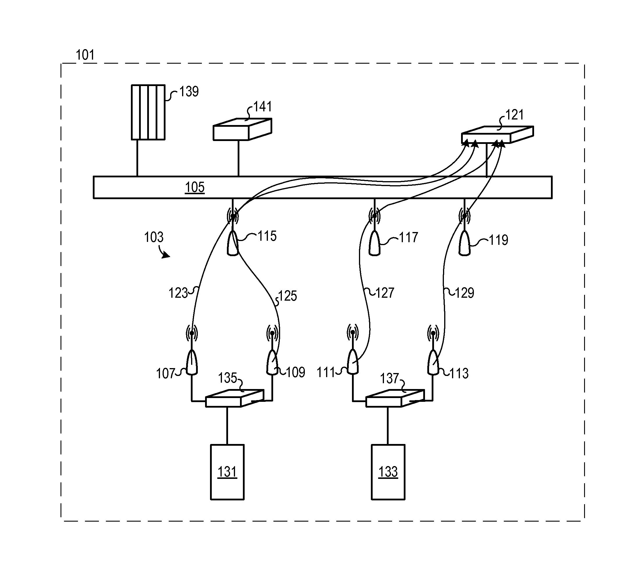
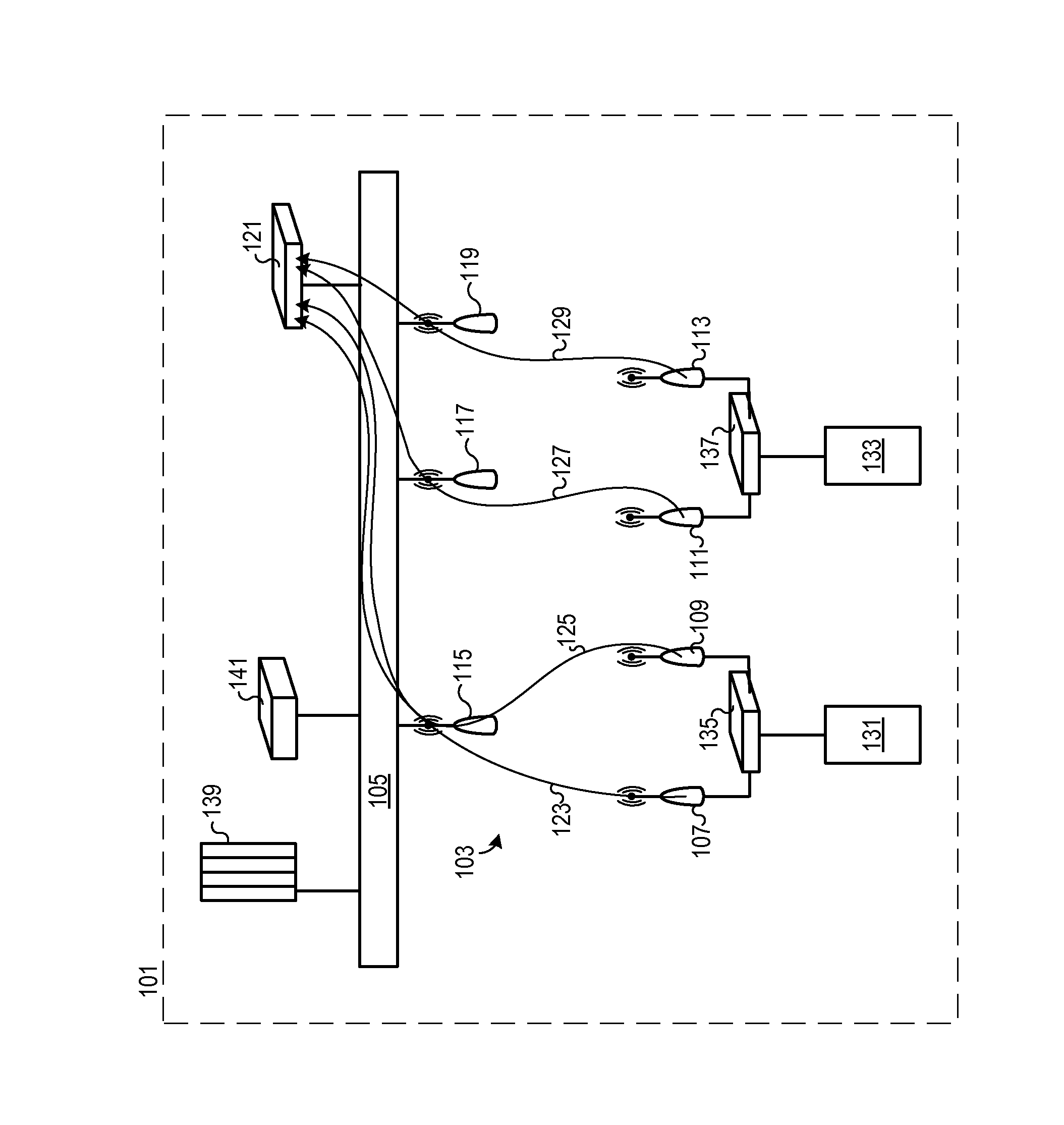
[0035]FIG. 1 shows a network system 101 according to one exemplary embodiment of the invention. The network system 101 includes a wireless network 103 which is connected to a backbone network 105. The wireless network 103 includes multiple clients 107, 109, 111, and 113. The clients 107, 109, 111, 113 are connected to the backbone network 105 via multiple access points 115, 117, and 119. A client control device 121 is also connected to the backbone network 105. Although it is not shown here, more than three access points may also be provided. In another embodiment of the invention which is not shown, fewer than three access points may also be provided.

[0036]A tunnel 123, 125, 127, and 129 is respectively established between clients 107, 109, 111, and 113 and the client control device 121. Data may be transmitted between the corresponding clients 107, 109, 111, 113 and the client control device 121 via tunnels 123, 125, 127, and 129. The tunnels 123, 125, 127, and 129 may also be ref...


PUM


Abstract

The invention relates to a method for controlling a network system, the network system including a wireless network to which a client is wirelessly connected, and a backbone network which is connected to the wireless network, having the following steps: (i) Establishing a tunnel between a client control device connected to the backbone network and the client for transmitting data between the client control device and the client, (ii) Sending status information from the client to the client control device via the tunnel, (iii) Evaluating the transmitted status information using the client control device, and (iv) Sending a control signal for controlling the client, which depends on the evaluated status information, from the client control device to the client via the tunnel. The invention further relates to a network system and a computer program.

Description

CROSS-REFERENCE TO RELATED APPLICATIONS[0001]German patent application 10 2010 007 670.8, filed Feb. 10, 2010, is incorporated herein by reference.FIELD OF INVENTION[0002]The invention relates to a method for controlling a network system, a network system, and a computer program.BACKGROUND OF THE INVENTION[0003]In industrial automation networks, layer 2-transparent communication between devices connected to clients, for example input / out stations, drive devices, or cameras, and a control system in the network, downstream from a wireless network infrastructure, by means of access points is necessary. The term “layers” hereinafter refers to the layers of the Open Systems Interconnection (OSI) reference layer model of the International Organization for Standardization (ISO), in particular when a Profinet or similar real-time Ethernet system is involved. Since there is no unequivocal standard for the transparent layer 2 linkage of networks, each manufacturer of network devices has devel...

Claims


Application Information

Patent Timeline
Patent Type & Authority Patents(United States)
IPC IPC(8): G06F15/173H04W76/02
CPCH04W76/022H04W76/12
Inventor PAPE, ANDREASWECZEREK, JUERGEN
Owner PHOENIX CONTACT GMBH & CO KG
Why Eureka
Try Eureka