Metamaterial for deflecting an electromagnetic wave

a technology of electromagnetic waves and metal materials, applied in shielding materials, cross-talk/noise/interference reduction, high-frequency circuit adaptations, etc., can solve the problems of electromagnetic wave deflecting, electromagnetic wave inertia of refractive indices, and inability to arbitrarily design the refractive indices of currently available materials

Active Publication Date: 2015-11-24
KUANG CHI INST OF ADVANCED TECH +1
View PDF6 Cites 0 Cited by
  • Summary
  • Abstract
  • Description
  • Claims
  • Application Information

AI Technical Summary

Benefits of technology

[0027]The metamaterial for deflecting an electromagnetic wave of the present disclosure has the following benefits: the metamaterial technologies are adopted to achieve deflection of the electromagnetic wave. The metamaterial is formed of a plurality of sheet layers, and by changing the man-made microstructures of each of the sheet layers, refractive indices of corresponding portions can be changed. Therefore, through overall design of the forms and structures of the man-made microstructures, refractive indices that change orderly can be obtained to form a man-made material with nonuniform refractive indices for deflecting the electromagnetic wave. Accordingly, the metamaterial of the present disclosure can satisfy requirements for deflecting various electromagnetic waves through different designs and arrangements of the man-made microstructures. Moreover, by virtue of the anisotropy of the unit cells, the exiting position of the electromagnetic wave can be controlled by rotating the optical axes of the unit cells.

Problems solved by technology

Materials capable of deflecting an electromagnetic wave (i.e., changing a propagating direction of the electromagnetic wave) are mainly inhomogenous materials; that is, inhomogeneity of the materials leads to unbalance in distribution of the refractive indices.
This kind of material for deflecting an electromagnetic wave is disadvantageous in that, the refractive indices of currently available materials are inherent and cannot be designed arbitrarily.
If refractive indices in some regions of the desired refractive index distribution cannot be obtained from natural materials currently available, the inhomogenous material as a whole will fail to satisfy the desired deflecting requirements.
However, arranging the man-made metal microstructures on the metamaterial substrate is not the sole way of changing the dielectric constants and the magnetic permeabilities of different points of the metamaterials to achieve different functions, and arranging the man-made metal microstructures on the metamaterial substrate requires use of a complex process, which is difficult to be implemented.

Method used


Image

  • Metamaterial for deflecting an electromagnetic wave
  • Metamaterial for deflecting an electromagnetic wave
  • Metamaterial for deflecting an electromagnetic wave

Examples


first embodiment

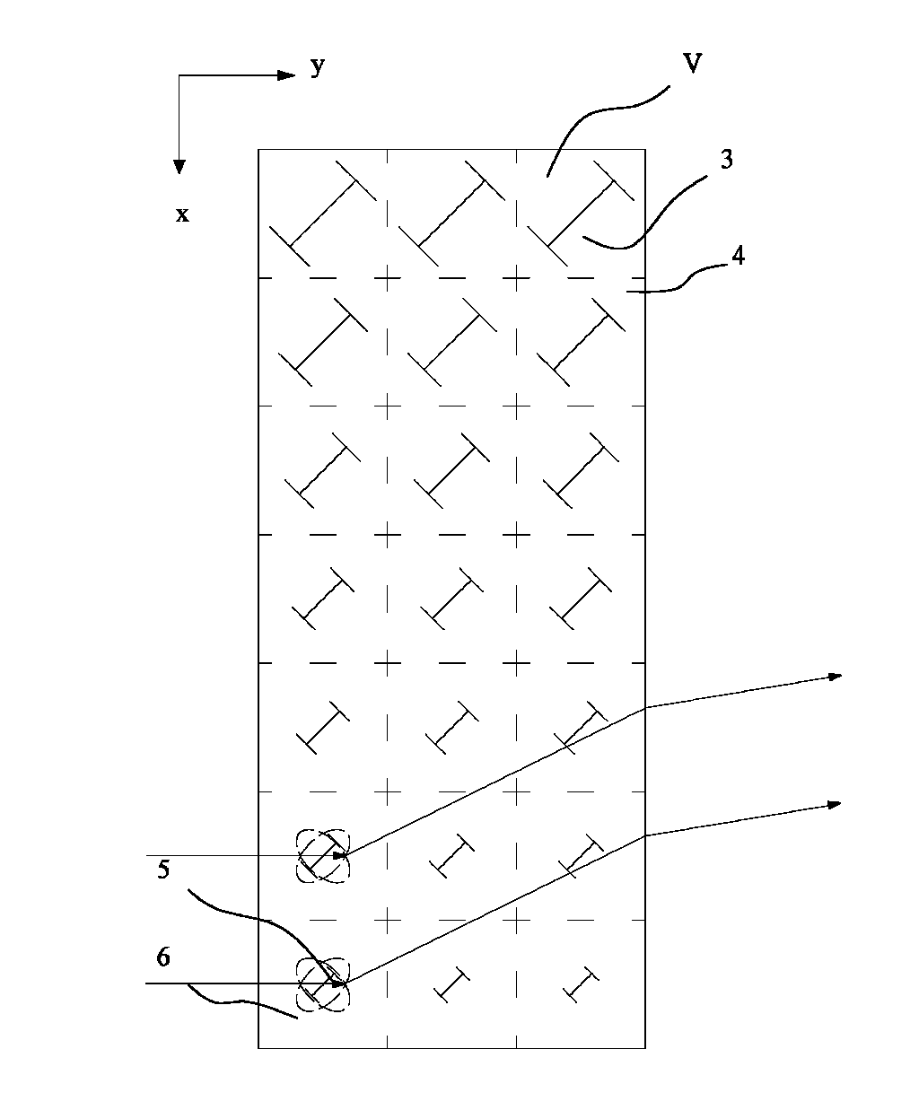
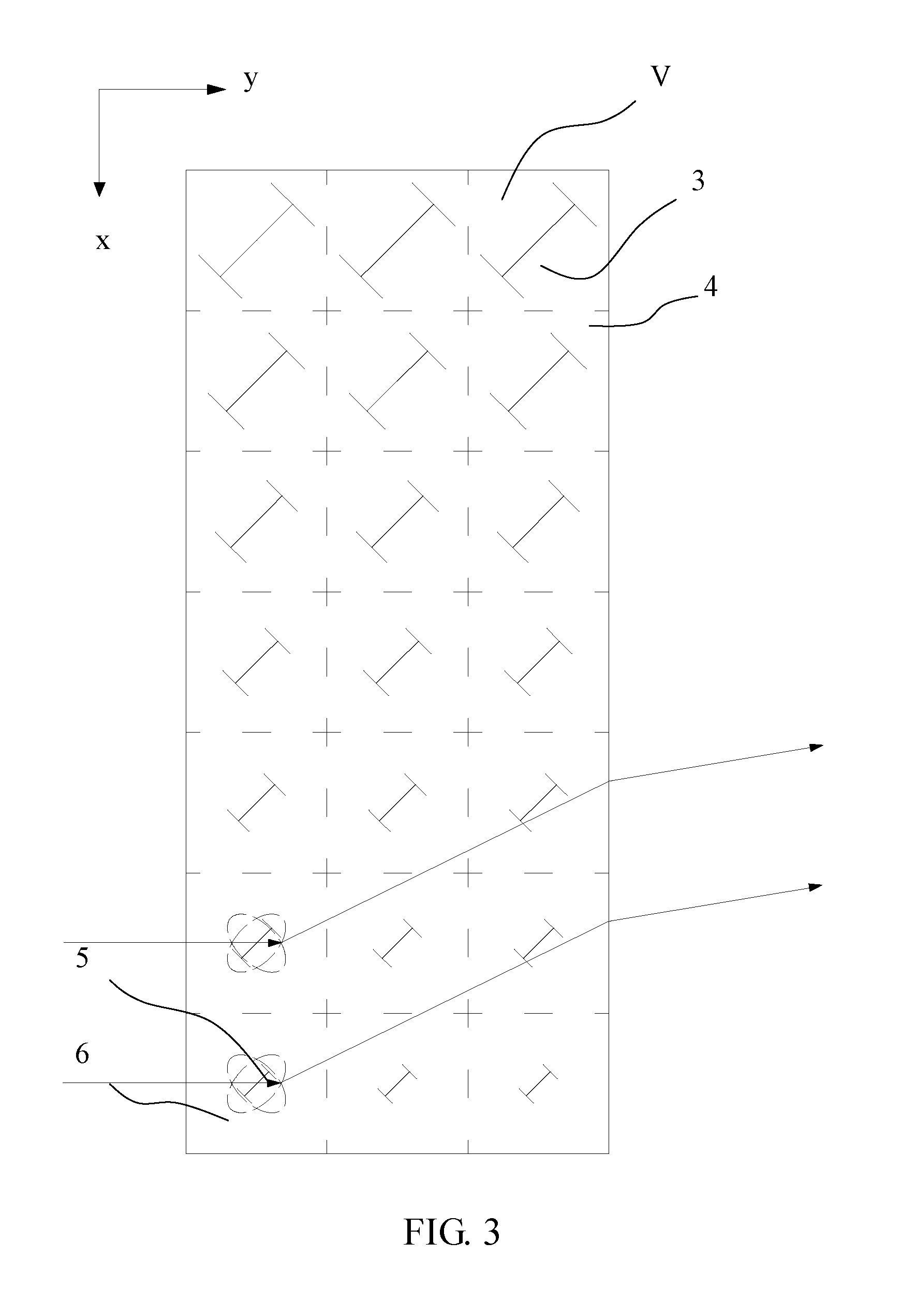
[0063]FIG. 3 is a schematic structural view of a functional layer 10 of a metamaterial according to the present disclosure. The man-made microstructures 3 are each a metal microstructure of an “I” form. The man-made microstructures 3 on each of the sheet layers 1 of the functional layer 10 are arranged in an array, and all have the same pattern of the “I” form. The man-made microstructures 3 arranged in the y direction decrease in size gradually, while the man-made microstructures 3 arranged in the x direction remain constant. As is known from experiments, for metal microstructures of the same pattern, the dielectric constants exhibited in the same unit cell is directly proportional to the sizes thereof. Therefore, in this embodiment, the regular distribution in size of the man-made microstructures actually also represents the regular distribution of the dielectric constants of the unit cells 4, and given that the magnetic permeability remains unchanged, also represents the regular ...

third embodiment

[0080]Referring to FIG. 7, FIG. 8 and FIG. 9, FIG. 7 is a schematic view of a cubic structure unit of the metamaterial for deflecting an electromagnetic wave according to the present disclosure, FIG. 8 is a schematic structural view of a metamaterial formed by stacking cubic structure units as shown in FIG. 7 in the x-y-z directions, and FIG. 9 is a front view of the metamaterial shown in FIG. 8. As shown in FIG. 9, the cubic structure unit comprises a substrate 11 and a pore 20 formed in the substrate 11. The pore 20 may be either a through-hole or not, but occupies a certain volume in the substrate 11 in both cases. In the metamaterial of this embodiment, a ratio of the volume of the pore 20 formed in the substrate 11 to the volume of the substrate 11 increases gradually in the y direction and remains constant in the x direction and the z direction, so the refractive indices decrease gradually in the y direction. Therefore, after the electromagnetic wave propagates through the met...

fourth embodiment

[0086]FIG. 11 is a front view of the metamaterial for deflecting an electromagnetic wave according to the present disclosure. In this embodiment, the ratio of the volume of the pore(s) 20 to the volume of the corresponding cubic structure unit remains constant for all the cubic structure units. The number, the size and the cross-sectional pattern of the pores 20 may be either the same or different for each of the cubic structure units so long as the ratio of the volume of the pore(s) 20 to the volume of the corresponding cubic structure unit remains constant for all the cubic structure units. In this embodiment, a case in which each of the cubic structure units has only one pore 20 and all the pores have the same size and the same circular cross-sectional pattern will be described as a preferred implementation. In such an implementation, the y direction is still taken as the first direction, and only a case in which the refractive indices decrease gradually in the y direction will b...


PUM


Abstract

A metamaterial for deflecting an electromagnetic wave is disclosed, which comprises a functional layer. The functional layer comprises a plurality of sheet layers parallel to each other, and each of the sheet layers comprises a sheet-like substrate and a plurality of man-made microstructures arranged in an array on the sheet-like substrate. The sheet-like substrate comprises a plurality of unit blocks, and each of the man-made microstructures and a corresponding one of the unit blocks occupied thereby form a unit cell. Refractive indices of the unit cells arranged in a first direction in each of the sheet layers decrease gradually. Each of the unit cells has an anisotropic electromagnetic parameter. Through use of the metamaterial of the present disclosure, deflection of the electromagnetic wave can be achieved.

Description

FIELD OF THE INVENTION[0001]The present disclosure generally relates to the technical field of electromagnetic communications, and more particularly, to a metamaterial for deflecting an electromagnetic wave.BACKGROUND OF THE INVENTION[0002]The communication industry mainly relies on use of electromagnetic waves for detection, positioning, communications and the like. The electromagnetic waves can be separated, converged, deflected and diverged by different materials or devices. Materials capable of deflecting an electromagnetic wave (i.e., changing a propagating direction of the electromagnetic wave) are mainly inhomogenous materials; that is, inhomogeneity of the materials leads to unbalance in distribution of the refractive indices. Specifically, differences in densities or species of materials can all lead to variations of the refractive indices.[0003]Prior art inhomogenous materials for deflecting an electromagnetic wave are usually formed by laminating multiple layers of materi...

Claims


Application Information

Patent Timeline
Patent Type & Authority Patents(United States)
IPC IPC(8): H01Q15/02H05K9/00H01Q15/00H05K1/02H05K3/46
CPCH05K9/0073H01Q15/0086H05K1/024H05K1/0236H05K3/4694H05K2201/09972
Inventor LIU, RUOPENGXU, GUANXIONGLUAN, LINJI, CHUNLINZHAO, ZHIYALI, YUEFENGYUE, YUTAO
Owner KUANG CHI INST OF ADVANCED TECH
Why Eureka
Try Eureka