Spring-loaded geared flap structure

a technology of spring-loaded flaps and stabilizers, which is applied in the direction of vessel construction, special-purpose vessels, vessel movement reduction by foils, etc., can solve the problem that there is no other flap rudder that is spring-loaded, and achieve the effect of more certain and safer ship operation

Inactive Publication Date: 2014-09-11
TOWNSEND CORNING
View PDF3 Cites 0 Cited by
  • Summary
  • Abstract
  • Description
  • Claims
  • Application Information

AI Technical Summary

Benefits of technology

[0012]The introduction of the spring element within the cylinder at the flap gear to rudder gear interface ensures that the rudder remains operational when either is bent and when debris wedges into the gearing. This makes operation of the ship more certain and safer than is the case when ex...

Problems solved by technology

There is no other flap rudde...

Method used


Image

  • Spring-loaded geared flap structure
  • Spring-loaded geared flap structure
  • Spring-loaded geared flap structure

Examples


Embodiment Construction

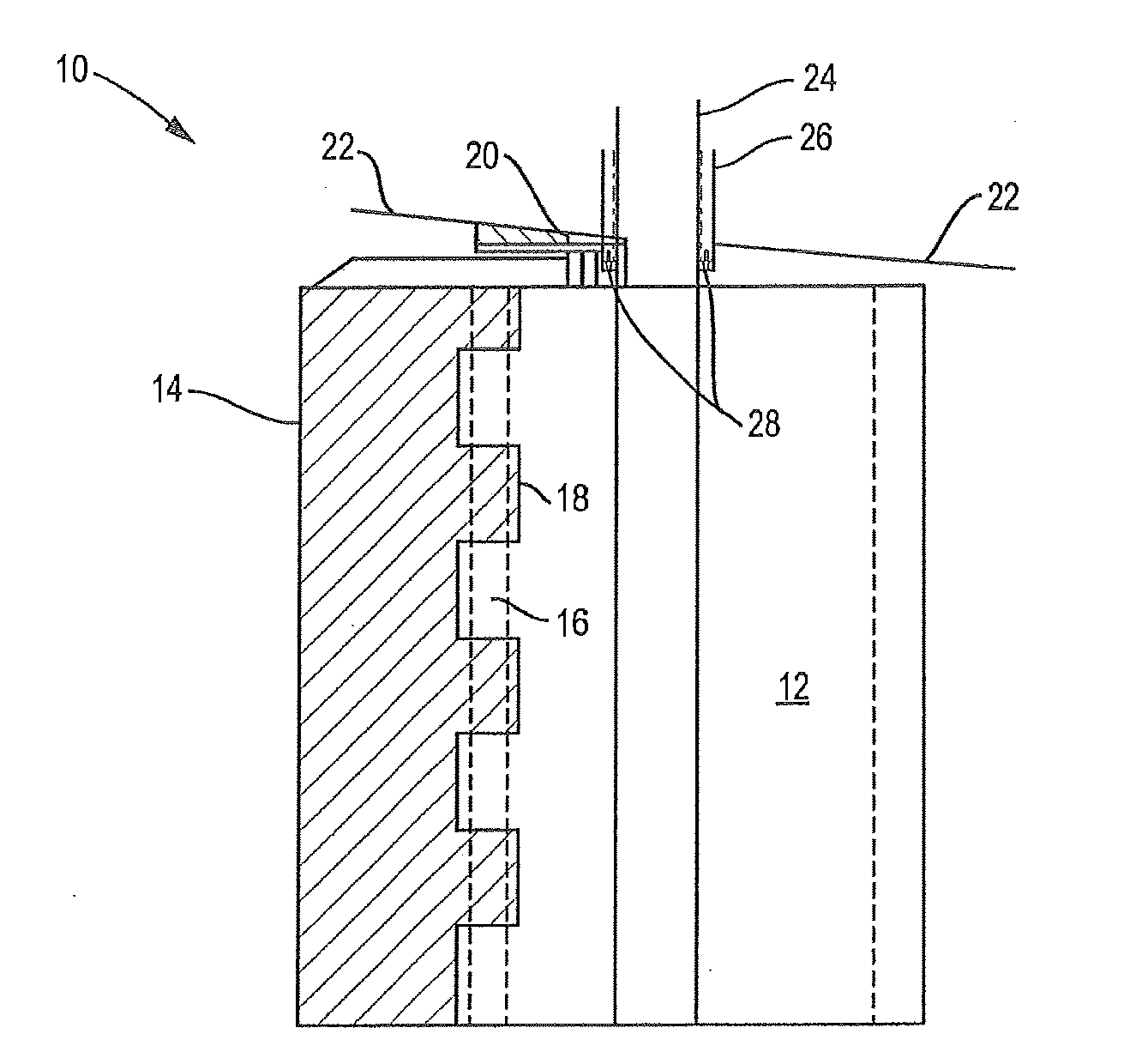
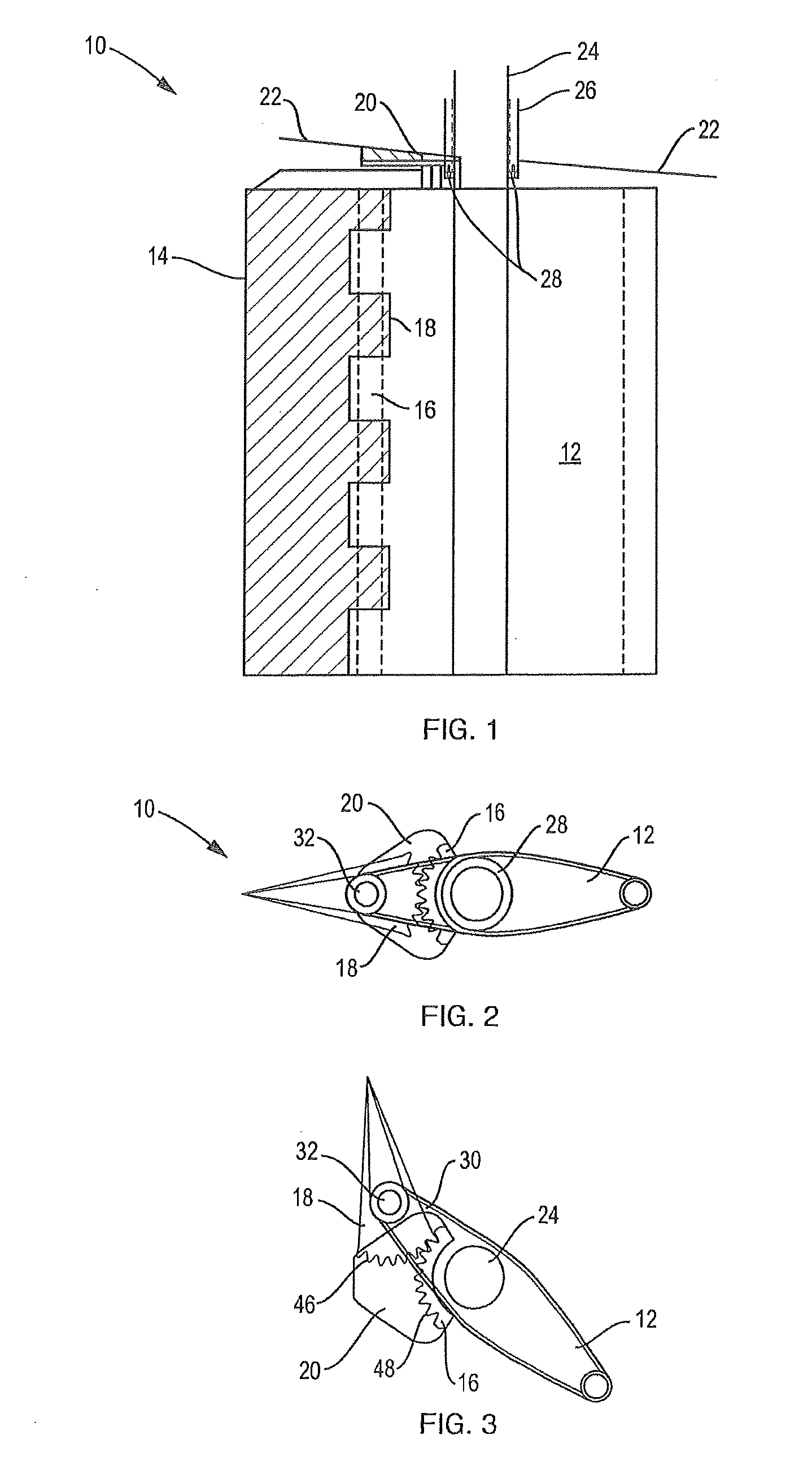
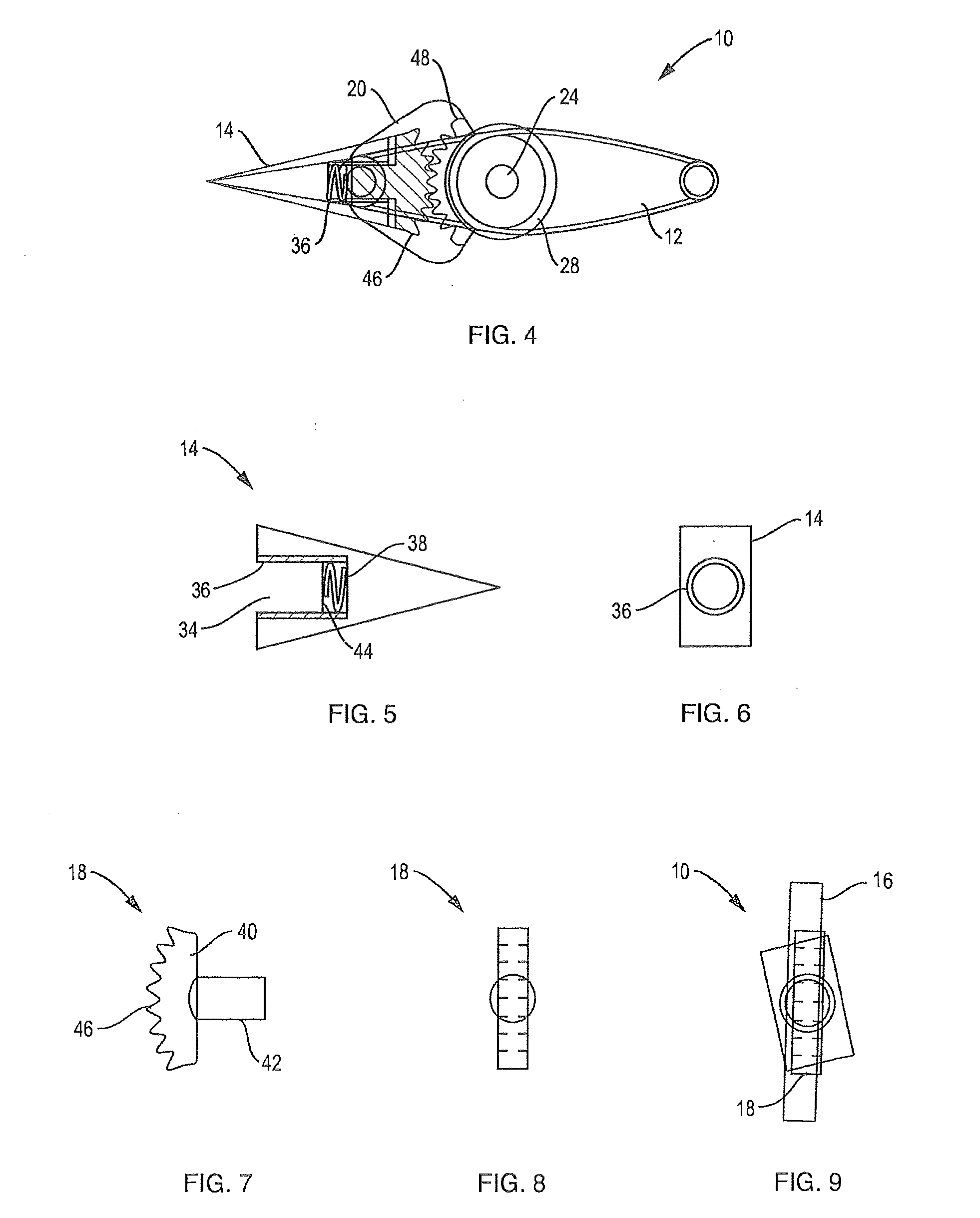
[0022]A spring-loaded geared flap rudder 10 of the present invention is shown in FIGS. 1-4. The flap rudder 10 includes a rudder member 12, a flap member 14, a rudder gear 16, a flap gear 18 and a gear cover 20. The flap rudder 10 is connected to a hull structure 22 of a ship aft of a propeller. Specifically, a rudder stock 24 of the rudder member 12 passes through a rudder port 26 of the hull structure 22 into an interior portion of the ship and joined to couplings and gearing controlled to cause movement of the rudder member 12. The rudder member 12 to hull 22 interface is sealed, such as with a split-ring seal 28, for example.

[0023]The rudder member 12 is rotatably mounted on the hull structure 20 by the rudder stock 24 such that the rudder member 12 is suspended from the hull structure 22. The flap member 14 is pivotally mounted on a trailing edge 30 of the rudder member 12 by way of a pivot rod 32.

[0024]The rudder gear 16 is connected to the hull structure 22, such as by weldin...


PUM


Abstract

A spring-loaded flap rudder or flap stabilizer adapted to be mounted to the hull structure of a ship. In a geared version of the invention, the rudder or stabilizer includes a member and a gear including teeth. The rudder or stabilizer also includes a flap member pivotally connected to the member with a component, such as a spring, arranged to limit jamming between the gear and a movable flap gear. The flap gear includes a rod movably engaged in a socket of the flap member and gear teeth for engagement with the teeth of the gear.

Description

BACKGROUND OF INVENTION[0001]1. Field of the Invention[0002]The present invention relates to marine craft. More particularly, the present invention relates to the rudders and stabilizers of marine craft. Still more particularly, the present invention relates to flap rudders and anti-roll stabilizers.[0003]2. Description of the Prior Art[0004]A rudder in the form of a pivotable plate or a displacement body is disposed at the stem of a ship. When the rudder is actuated, it is pivoted by a controlled angle of deflection. That movement develops a hydrodynamic transverse force which acts on the rudder and correspondingly on the stem of the ship. This force produces the turning torque required to steer the ship. This hydrodynamic transverse force produces a torque on the rudder with respect to the rudder stock which is to be supplied by the steering gear.[0005]There are single member rudders, flap rudders and geared flap rudders. The current basic arrangement for a geared flap rudder incl...

Claims


Application Information

Patent Timeline
IPC IPC(8): B63B39/06B63H25/38
CPCB63H25/381B63B39/06B63H25/10
Inventor TOWNSEND, CORNING
Owner TOWNSEND CORNING
Why Eureka
Try Eureka