Multiprocessor system snoop scheduling mechanism for limited bandwidth snoopers

a multi-processor system and scheduling mechanism technology, applied in the field of computer systems, can solve the problems of poor performance, processing element to miss, and the manner in which these operations are carried ou

Inactive Publication Date: 2002-09-12
IBM CORP
View PDF0 Cites 0 Cited by
  • Summary
  • Abstract
  • Description
  • Claims
  • Application Information

AI Technical Summary

Benefits of technology

[0024] It is therefore one object of the present invention to provide an improved method of handling cache operations in a multiprocessor computer system.
[0025] It is another object of the present invention to provide such a method that efficiently schedules snoop operations between processing units and their caches.
[0026] It is yet another object of the present invention to provide a computer system which ensures that certain operations (e.g., kill-type operations) are executed within a limited time frame and without repeated retry attempts.

Problems solved by technology

However, it is possible for a processing element to miss a write to the memory location.
While these various cache operations ensure proper coherency and allow for the sharing of memory between the different processing units, there are still several problems regarding the manner in which these operations are carried out.
This condition can create poor performance (or livelock situations) because the snoopers are not synchronized, and there is no assurance that snoopers with limited bandwidth will able to snoop each operation.
This approach leads to very poor odds for getting a kill-type operation through cleanly (i.e. without being retried).
This factor will thus lead to further retries and delays.
In many cases, these write operations take multiple cycles such that once initiated, a directory read (i.e. snoop) cannot be immediately performed.

Method used


Image

  • Multiprocessor system snoop scheduling mechanism for limited bandwidth snoopers
  • Multiprocessor system snoop scheduling mechanism for limited bandwidth snoopers
  • Multiprocessor system snoop scheduling mechanism for limited bandwidth snoopers

Examples


Embodiment Construction

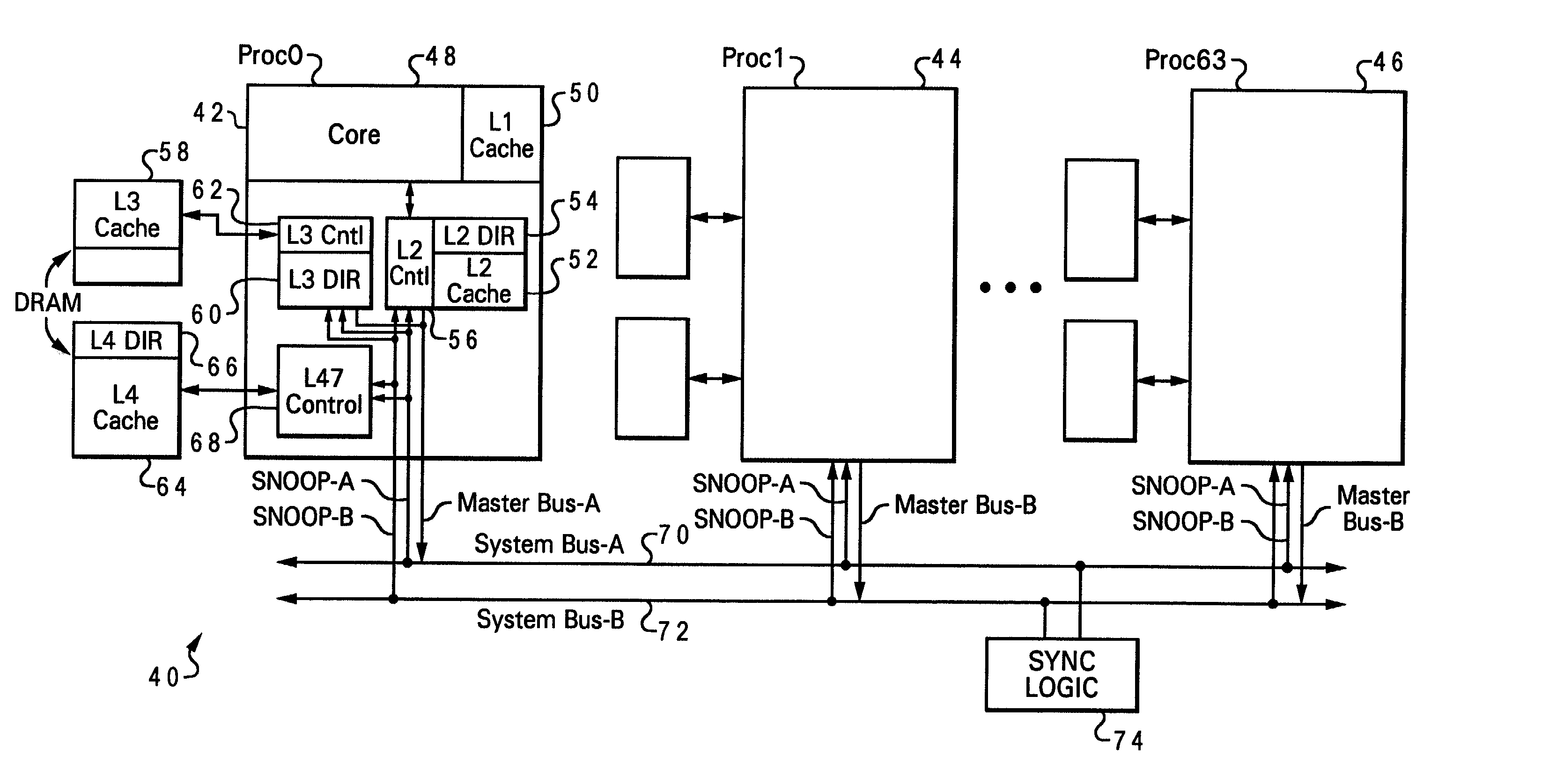
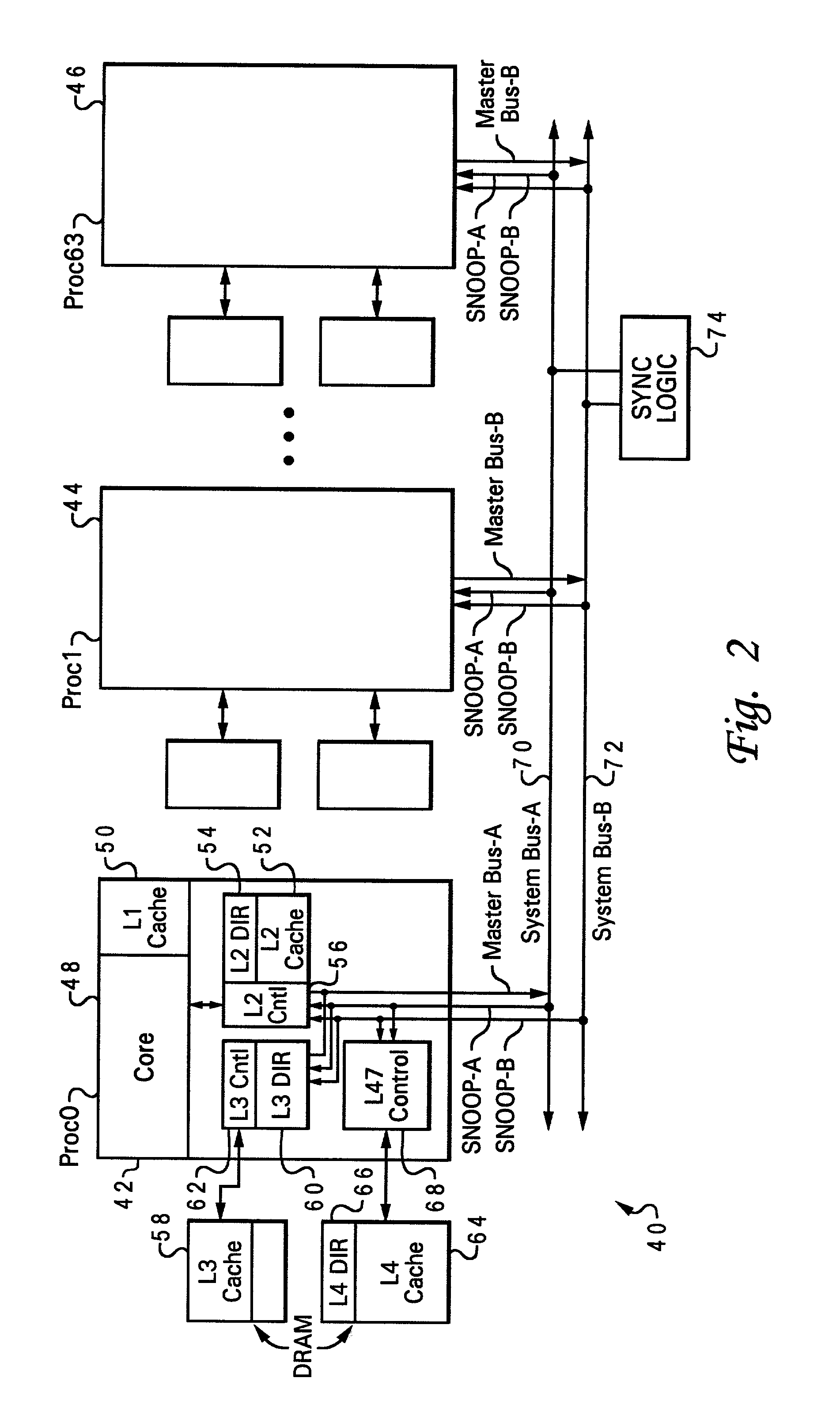
[0035] With reference now to FIG. 2, there is depicted one embodiment 40 of a multiprocessor computer system. In this example, multiprocessor computer system 40 is a very large, symmetric multiprocessor (SMP) having 64 processing units, including processing units 42, 44 and 46 (processing units 0, 1 and 63). As illustrated with processing unit 44, each of these processing units includes a processing core 48, an L1 cache 50, an L2 cache 52 which includes L2 directory 54 and L2 controller 56, an L3 cache 58 which includes L3 directory 60 and L3 controller 62, and an L4 cache 64 which includes L4 directory 66 and L4 controller 68. Dual system buses, that is, system bus A 70 and system bus B 72 are provided for increased address bandwidth. A given master is connected to only one of these two buses, and can only issue a request on their one respective bus, but all snoopers see both system bus A 70 and system bus B 72.

[0036] In the preferred embodiment, L2 directory 54 is relatively fast ...


PUM


Abstract

A multiprocessor computer system in which snoop operations of the caches are synchronized to allow the issuance of a cache operation during a cycle which is selected based on the particular manner in which the caches have been synchronized. Each cache controller is aware of when these synchronized snoop tenures occur, and can target these cycles for certain types of requests that are sensitive to snooper retries, such as kill-type operations. The synchronization may set up a priority scheme for systems with multiple interconnect buses, or may synchronize the refresh cycles of the DRAM memory of the snooper's directory. In another aspect of the invention, windows are created during which a directory will not receive write operations (i.e., the directory is reserved for only read-type operations). The invention may be implemented in a cache hierarchy which provides memory arranged in banks, the banks being similarly synchronized. The invention is not limited to any particular type of instruction, and the synchronization functionality may be hardware or software programmable.

Description

CROSS-REFERENCE TO RELATED APPLICATIONS[0001] The present invention is related to the following applications filed concurrently with this application, each of which is hereby incorporated: U.S. patent application Ser. No. 09 / ______ entitled "MULTIPROCESSOR SYSTEM SNOOP SCHEDULING MECHANISM FOR LIMITED BANDWIDTH SNOOPERS PERFORMING DIRECTORY UPDATE" (attorney docket no. AUS920000672US1); U.S. patent application Ser. No. 09 / ______ entitled "MULTIPROCESSOR SYSTEM SNOOP SCHEDULING MECHANISM FOR LIMITED BANDWIDTH SNOOPERS WITH BANKED DIRECTORY IMPLEMENTATION" (attorney docket no. AUS920000673US1); and U.S. patent application Ser. No. 09 / ______ entitled "MULTIPROCESSOR SYSTEM SNOOP SCHEDULING MECHANISM FOR LIMITED BANDWIDTH SNOOPERS THAT USES DYNAMIC HARDWARE / SOFTWARE CONTROLS" (attorney docket no. AUS920000674US1).BACKGROUND OF THE INVENTION[0002] 1. Field of the Invention[0003] The present invention generally relates to computer systems, and more particularly to a method of efficiently ...

Claims


Application Information

Patent Timeline
Patent Type & Authority Applications(United States)
IPC IPC(8): G06F12/08
CPCG06F12/0831
Inventor ARIMILLI, RAVI KUMARFIELDS, JAMES STEPHEN JR.GHAI, SANJEEVGUTHRIE, GUY LYNNJOYNER, JODY B.
Owner IBM CORP
Why Eureka
Try Eureka