Techniques for representing and processing geometry within a graphics processing pipeline

a graphics processing pipeline and pipeline technology, applied in the field of graphics processing, can solve the problems of limited graphics processing pipeline throughput, limited graphics processing pipeline overall performance, and unit having fixed throughput and limited scalability,

Active Publication Date: 2020-03-24
NVIDIA CORP
View PDF16 Cites 0 Cited by
  • Summary
  • Abstract
  • Description
  • Claims
  • Application Information

AI Technical Summary

Benefits of technology

[0007]One advantage of the disclosed techniques is that a graphics processing pipeline may implement the techniques instead of implementing a primitive distributor, vertex processing units, and geometry shading units. As a result, the performance of the graphics processing pipeline is not limited by the fixed throughput of the primitive distributor. Further, because multiple cooperative threads execute the shading program, the graphics processing pipeline may perform certain operations earlier and more efficiently relative to a conventional graphics processing pipeline.

Problems solved by technology

One limitation of conventional graphics processing pipelines is that the throughput of the graphics processing pipeline is limited by the throughput of the primitive distributor.
More particularly, the primitive distributor typically is a fixed-function hardware unit having a fixed throughput and limited scalability.
Consequently, as the memory bandwidth and number of streaming multiprocessors increase, the primitive distributor limits the overall performance of the graphics processing pipeline.
Another limitation of conventional graphics processing pipelines is that the applicable programming model is inflexible.
Among other things, the programming model does not allow applications to execute certain operations earlier in the pipeline to make overall execution more efficient.
Because a given thread processes a given vertex independently of the vertices being processed by other threads, there is no good way to program the vertex processing unit to perform culling operations to discard non-visible primitives at the vertex processing stage of the graphics processing pipeline.
Because the vertex processing unit cannot be programmed to cull non-visible primitives, downstream units in the graphics processing pipeline end up performing unnecessary graphics operations on those non-visible primitives, thus wasting both processing resources and power.

Method used


Image

  • Techniques for representing and processing geometry within a graphics processing pipeline
  • Techniques for representing and processing geometry within a graphics processing pipeline
  • Techniques for representing and processing geometry within a graphics processing pipeline

Examples


Embodiment Construction

[0020]In the following description, numerous specific details are set forth to provide a more thorough understanding of the present invention. However, it will be apparent to one of skilled in the art that the present invention may be practiced without one or more of these specific details.

System Overview

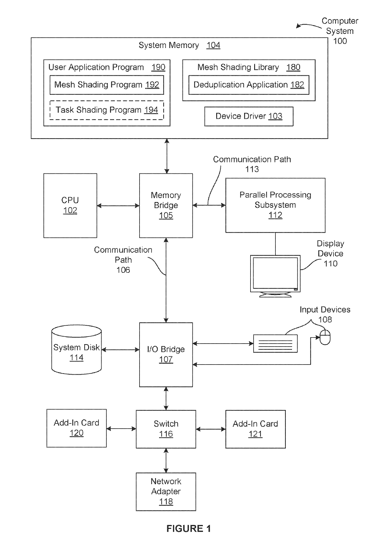
[0021]FIG. 1 is a block diagram illustrating a computer system 100 configured to implement one or more aspects of the present invention. As shown, computer system 100 includes, without limitation, a central processing unit (CPU) 102 and a system memory 104 coupled to a parallel processing subsystem 112 via a memory bridge 105 and a communication path 113. In some embodiments, the computer system 100 is a game console. Memory bridge 105 is further coupled to an I / O (input / output) bridge 107 via a communication path 106, and I / O bridge 107 is, in turn, coupled to a switch 116.

[0022]In operation, I / O bridge 107 is configured to receive user input information from input devices 108, suc...


PUM


Abstract

In various embodiments, a parallel processor implements a graphics processing pipeline that generates rendered images via a shading program. In operation, the parallel processor causes a first set of execution threads to execute the shading program on a first portion of the input mesh to generate first geometry stored in an on-chip memory. The parallel processor also causes a second set of execution threads to execute the mesh shading program on a second portion of the input mesh to generate second geometry stored in the on-chip memory. Subsequently, the parallel processor reads the first geometry and the second geometry from the on-chip memory, and performs operations on the first geometry and the second geometry to generate a rendered image derived from the input mesh. Advantageously, unlike conventional graphics processing pipelines, the performance of the graphics processing pipeline is not limited by a primitive distributor.

Description

BACKGROUND OF THE INVENTIONField of the Invention[0001]Embodiments of the present invention relate generally to graphics processing and, more specifically, to techniques for representing and processing geometry within a graphics processing pipeline.Description of the Related Art[0002]A conventional graphics processing pipeline typically includes a single fixed-function hardware unit known as the primitive distributor. The primitive distributor collects vertex data associated with high-order surfaces, graphics primitives, and the like, from a front end unit and constructs corresponding batches of work, where each batch of work includes vertex data that defines multiple primitives. The batches of work are then processed by programmable execution units also included in the graphics processing pipeline. During execution, the batches of work are distributed across a set of streaming multiprocessors that are configured to execute a large number of threads in parallel to perform graphics o...

Claims


Application Information

Patent Timeline
Patent Type & Authority Patents(United States)
IPC IPC(8): G06T15/00G06T15/04G06T17/20G06T17/10G06T15/80
CPCG06T17/10G06T15/04G06T15/80G06T15/005G06T17/20
Inventor HAKURA, ZIYADURALSKY, YURYKUBISCH, CHRISTOPHBOUDIER, PIERREMORETON, HENRY
Owner NVIDIA CORP
Why Eureka
Try Eureka