Multiwell plate

a multi-well plate and cell technology, applied in the field of cell biology, can solve the problems of difficult high-throughput imaging (for example morphological studies), difficult to find specific individual cells for observation, and inconvenient study of individual cells or even small groups of cells on multi-well plates, etc., to delay the proliferation of living cells held

Active Publication Date: 2015-12-01
SENG ENTERPRISES
View PDF228 Cites 48 Cited by
  • Summary
  • Abstract
  • Description
  • Claims
  • Application Information

AI Technical Summary

Benefits of technology

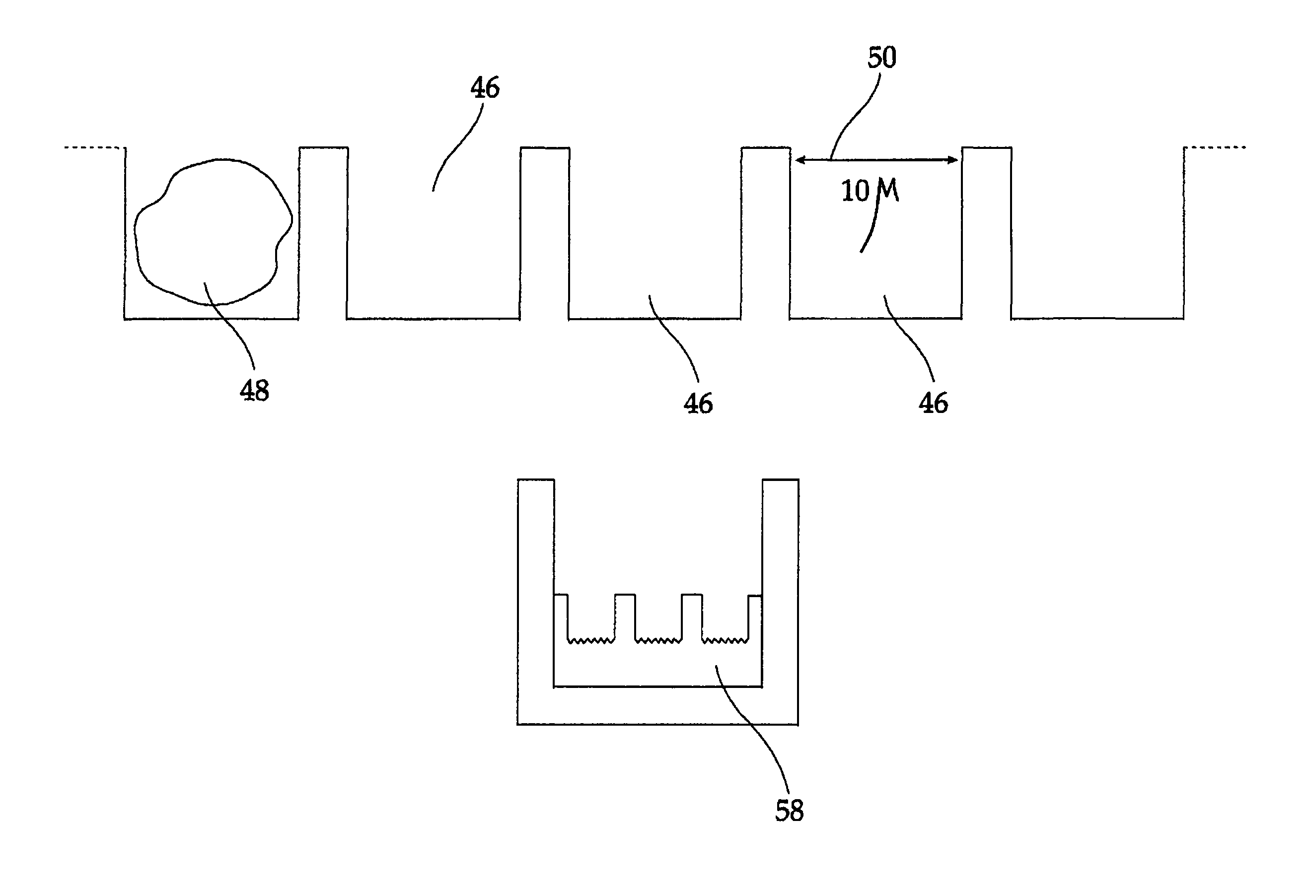
[0074]As noted above, whatever method is used for making a multiwell plate of the present invention, it is often desired to coat the plurality of picowells, especially the inside surface of picowells with some material. Coating the inside surface of a picowell allows modification of the properties of the picowell, for example to reduce cytotoxicity, to change physical properties such as solvent resistance or permeability or to delay proliferation of cells held in a respective picowell. In an embodiment of the method of the present invention, coating the inside surface of picowells comprises (i) applying a precursor fluid to inside surfaces of the picowells; and (ii) solidifying the precursor fluid so as to form the layer. Suitable methods of solidifying include but are not limited to heating the precursor fluid, cooling the precursor fluid, polymerizing the precursor fluid, cross-linking the precursor fluid, curing the precursor fluid, irradiating the precursor fluid, illuminating the precursor fluid, gelling the precursor fluid, exposing the precursor fluid to a fixative and waiting a period of time.
[0078]In a preferred embodiment of the present invention, the matrix is configured to substantially delay the proliferation of living cells held therein.

Problems solved by technology

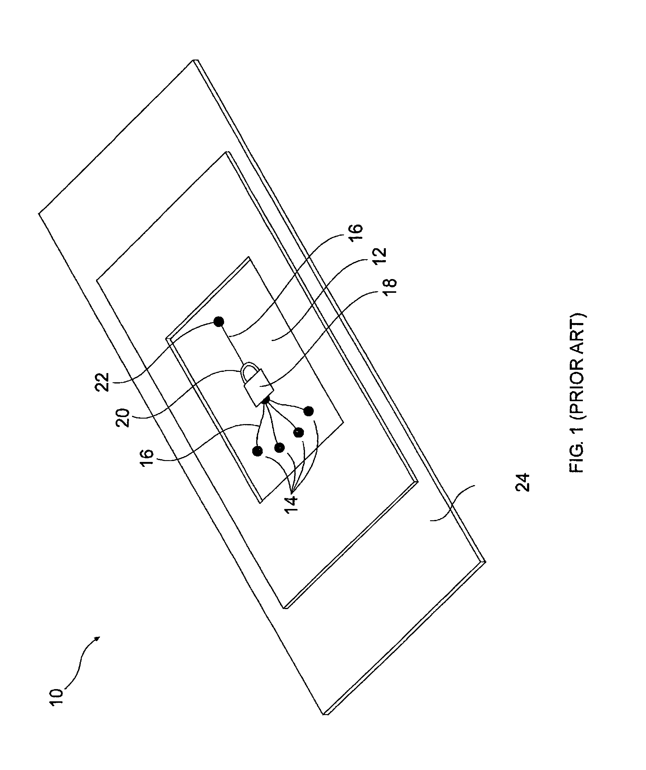
Although exceptionally useful for the study of large groups of cells, multiwell plates are not suitable for the study of individual cells or even small groups of cells due to the large, relative to the cellular scale, size of the wells.
When cells float about in a well, specific individual cells are not easily found for observation.
Such variability in location makes high-throughput imaging (for example for morphological studies) challenging as acquiring an individual cell and focusing thereon is extremely difficult.
Such variability in location also makes high-throughput signal processing (for example, detection of light emitted by a single cell through fluorescent processes) challenging as light must be gathered from the entire area of the well, decreasing the signal to noise ratio.
Further, a cell held in a well of a multiwell plate well can be physically or chemically manipulated (for example, isolation or movement of a single selected cell or single type of cell, changing media or introducing drugs) only with difficulty.
An additional disadvantage of multiwell plates is during the study of cells undergoing apoptosis.
However, once a cell begins the apoptosis process, the adhesion of the cell to the bottom of the well is no longer sufficient: the cell detaches from the bottom and is carried away by incidental fluid currents in the well.
The fact that the cells are not free-floating but are bound to the plate through some interaction necessarily compromises the results of experiments performed.
Further, the suction required to hold cells in picowells of a carrier of U.S. Pat. No. 4,729,949 deforms held cells and makes a significant portion of the cell membranes unavailable for contact, both factors that potentially compromise experimental results.
Study of cells with non-fluorescence based methods generally gives poor results due to reflections of light from the carrier.
There are a number of disadvantages to the teachings of PCT patent application US99 / 04473.
The fact that emitted light travels through an optical fiber leads to loss of time-dependent and phase information.
Despite the utility of the device taught in PCT patent applications IL01 / 00992, the use of the device is too labor intensive for certain high-throughput implementations.
Amongst other reasons the large amount of labor is required because there exist no commercially available robotic systems optimized for use with the devices.

Method used


Image

  • Multiwell plate
  • Multiwell plate
  • Multiwell plate

Examples


Embodiment Construction

[0110]The present invention is of a mulitwell plate having a plurality of picowells on the bottom of the wells of the plate. The present invention is also of methods of producing a mulitwell plate of the present invention. The present invention is also of a device comprising an array of living cells held in a non-fluid matrix. The present invention is also of a method of handling living cells by providing an ordered array of living cells immobilized in a non-fluid matrix, contacting the living cells with a stimulus; and detecting a response to the stimulus. The present invention is also of a method of producing an ordered array of living cells.

[0111]The principles and uses of the teachings of the present invention may be better understood with reference to the accompanying description, figures and examples. In the figures, like reference numerals refer to like parts throughout.

[0112]Before explaining at least one embodiment of the invention in detail, it is to be understood that the...


PUM

PropertyMeasurementUnit
volumeaaaaaaaaaa
diameteraaaaaaaaaa
volumeaaaaaaaaaa

Abstract

A mulitwell plate having a plurality of picowells on the bottom of the wells of the plate as well as methods of producing the mulitwell plate are provided. Provided is also a method of handling living cells by providing an ordered array of living cells immobilized in a non-fluid matrix, contacting the living cells with a stimulus; and detecting a response to the stimulus. The present invention is also of a method of producing an ordered array of living cells.

Description

RELATED APPLICATIONS[0001]This application is a National Phase Application of PCT Application No. PCT / IL2004 / 000661 having International Filing Date of Jul. 20, 2004, which claims the benefit of priority from U.S. Provisional Patent Application No. 60 / 488,408, filed on Jul. 21, 2003, U.S. Provisional Patent Application No. 60 / 488,409, filed on Jul. 21, 2003, U.S. Provisional Patent Application No. 60 / 517,073, filed on Nov. 5, 2003, U.S. Provisional Patent Application No. 60 / 517,084, filed on Nov. 5, 2003, U.S. Provisional Patent Application No. 60 / 544,356, filed on Feb. 17, 2004, U.S. Provisional Patent Application No. 60 / 544,357 filed on Feb. 17, 2004, and is also a Continuation-In-Part (CIP) of PCT Application No. PCT / IL2004 / 000571, filed on Jun. 27, 2004.[0002]This application is also a Continuation-In-Part (CIP) of U.S. application Ser. No. 10 / 561,839, filed on Jun. 5, 2006, now abandoned, which is a National Phase of PCT Patent Application No. PCT / IL2004 / 000571, filed on Jun. 2...

Claims


Application Information

Patent Timeline
Patent Type & Authority Patents(United States)
IPC IPC(8): C12M3/00C12M1/32B01L3/00C12N11/04G01N33/50C12M1/00
CPCC12M23/12C12N11/04G01N33/5008B01L3/5085Y10T29/49B01L2200/0668B01L2200/12B01L2300/04B01L2300/069B01L2300/0819B01L2300/0829B01L2300/0893B01L2300/0896B01L2400/0409B01L2400/0454B01L2400/0457B01L2400/0487C12M23/20B29C39/026B29C65/002B29C65/48B29K2101/12B29L2009/00B29L2031/712
Inventor DEUTSCH, MORDECHAIHERZBERG, MAXTIROSH, REUVENDEUTSCH, ASSAF
Owner SENG ENTERPRISES
Why Eureka
Try Eureka