
Dielectric dryer drum

a dryer drum and dielectric technology, applied in drying machines, lighting and heating apparatus, furnaces, etc., can solve problems such as problems in using a microwave oven as a dryer (basically the method used by ben-shmuel) and achieve the effects of uniform water removal, sufficient heating energy, and improved heating energy penetration

Active Publication Date: 2015-12-01
LG ELECTRONICS INC
View PDF76 Cites 29 Cited by
  • Summary
  • Abstract
  • Description
  • Claims
  • Application Information

AI Technical Summary

Benefits of technology

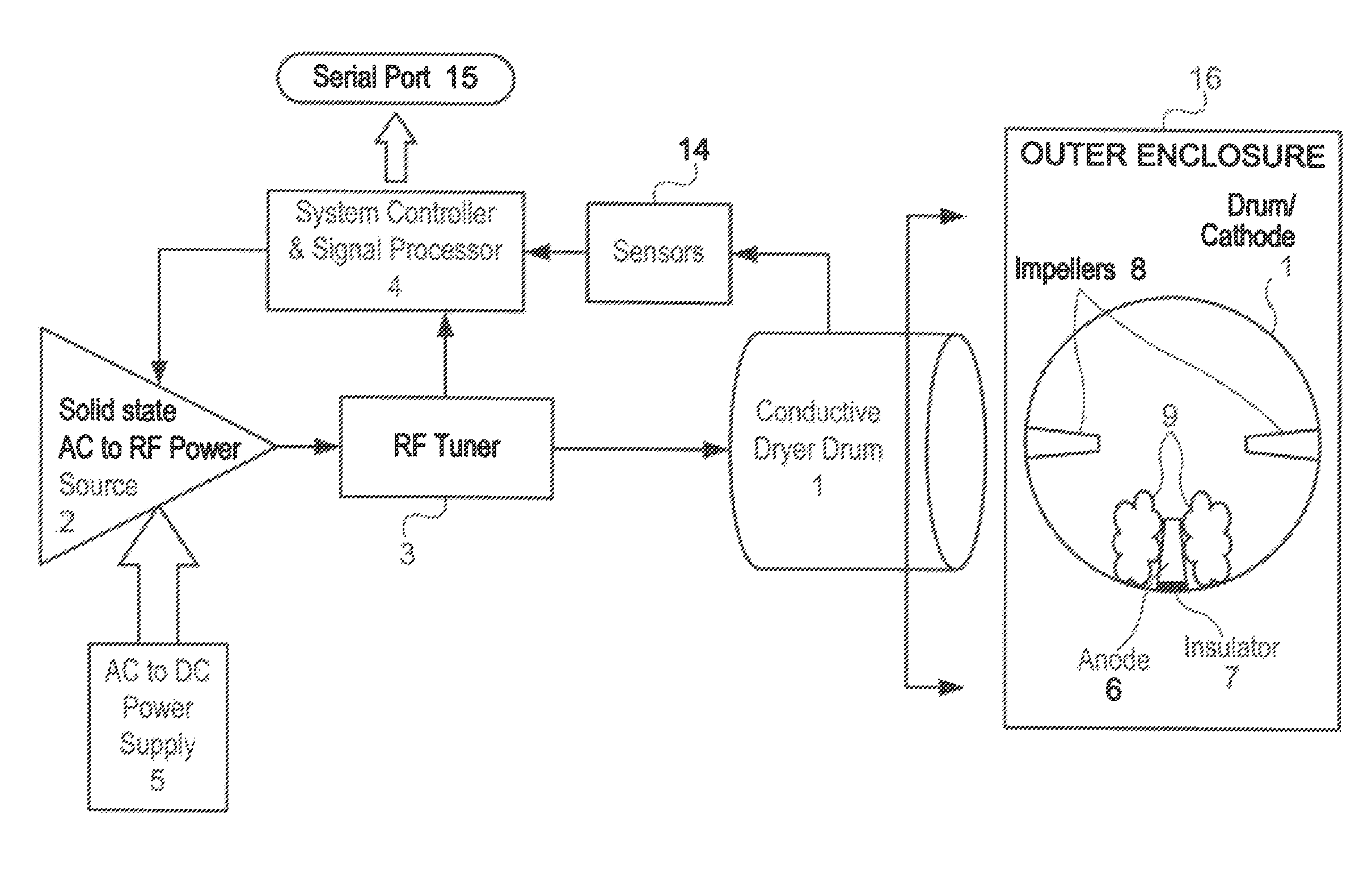
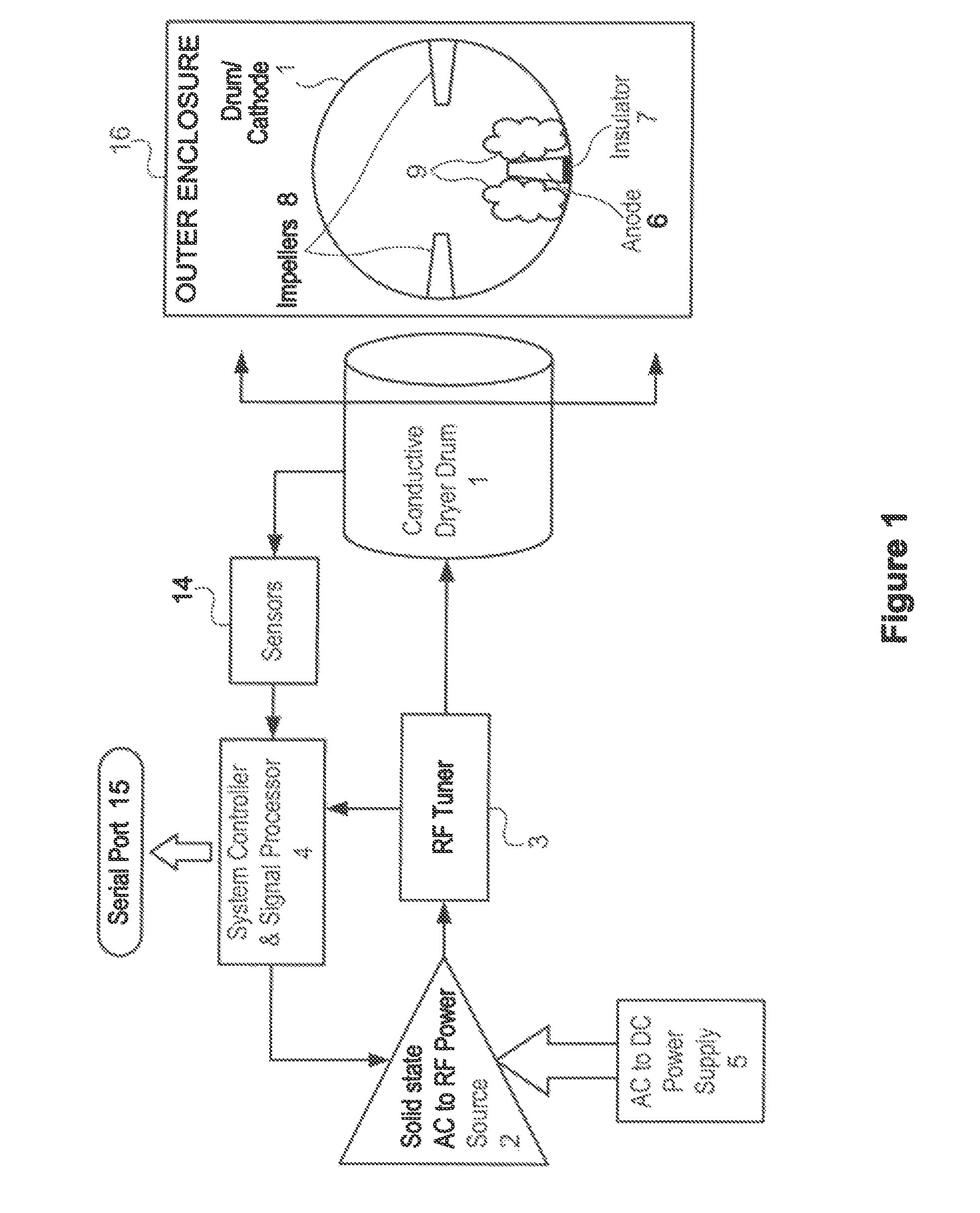
[0013]In the present invention, an optimized, single, low RF frequency power source 2 is used, providing the heating energy in an enclosure 16, which can comprise a conventional rotating drum 1. Efficient delivery of the RF power 2 to the load 9 is achieved by maintaining close electrical contact of the load 9 to both an anode 6 and cathode 1 of the apparatus, offering an optimum solution in creating an improved highly energy-efficient clothes dryer. Impellers 8 are used to randomize the tumbling of the load 9 to improve evaporation of moisture in the load.
[0017]We therefore use low frequency RF power (for example, in the range of 10 MHz to 100 MHz), where the longer wavelength (29.979 meters to 2.9979 meters) assures a better penetration of the heating energy into the drying object, and insuring a more uniform water removal.
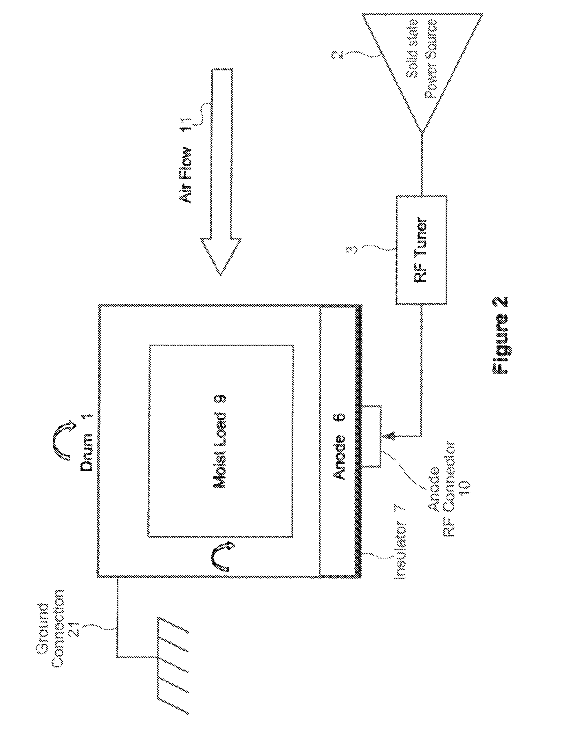
[0018]Here is why we want electrical contact of the clothes to both the anode 6 and cathode 1 of our capacitive enclosure. At the low frequencies we use (in the range of 10 MHz to 100 MHz), it is not possible to insert an antenna small enough to match the load 9 impedance to the energy feed structure 2, 3, 10 used to deliver the power to the load 9. Our close electrical contact to the load 9 is a key factor that is missing in all the previous attempts to develop a low frequency RF fabric dryer. By substituting the electric field approach of energy delivery to the load 9 by a continuous electrical contact that minimizes the air gap between the clothes 9 and the electrodes 6, 1 (and therefore minimizes the parasitic series air capacitance), we are assured of an efficient transfer of heating energy 2 to the load 9.

Problems solved by technology

It is well known by the consumer that trying to use a microwave oven as a dryer (which is basically the method used by Ben-Shmuel) has problems.
is valid only for high RF frequencies (mostly microwaves) such as Ben-Shmuel's frequencies, where the wavelength is short and the heating is non uniform due to the fact that the energy does not penetrate into the material, heating only the surface.

Method used


Image

  • Dielectric dryer drum
  • Dielectric dryer drum
  • Dielectric dryer drum

Examples


first embodiment

[0067]In a first embodiment, the anode 6 is coupled to the RF tuner 3 by using a fixed contact brush 204 that is coupled to tuner 3 and makes contact with a rotating brush commutator 202 that is coupled to the rotating anode 6, as shown in FIG. 6(a).

second embodiment

[0068]In a second embodiment, shown in FIG. 6(b), anode 6 is coupled to the RF source 2 and tuner 3 via a capacitive disc coupler comprising three axially aligned discs 208, 209, 210. In this embodiment, the inner (rightmost) disc 208 rotates and is coupled to the anode 6, the center disc 209 is an insulator, and the outer (leftmost) disc 210 is stationary and coupled to tuner 3.

third embodiment

[0069]In a third embodiment, anode 6 is coupled to RF source 2 and tuner 3 via a single capacitive cylinder disc coupler, as shown in FIG. 6(c). In this embodiment, the inner (rightmost) cylinder 214 is rotating and connected to anode 6, dielectric spacer 216 radially surrounds cylinder 214 and is an insulator, and the outer (leftmost) disc 212 is stationary and coupled to tuner 3.

[0070]FIG. 7 illustrates an embodiment of the present invention in which variable anode element coupling is employed to implement the capacitive disc coupler of FIG. 6(b). The coupling comprises three concentric plates: fixed plate 210, insulator 209, and rotating plate 208, as shown in the FIG. 7(b) side view and in FIG. 6(b). Typically, only a portion 222 of fixed plate 210 needs to be electrically conductive, as shown in the FIG. 7(a) rear view. Conductive capacitor plate 232 is attached to the anode 6, as shown in the FIG. 7(d) side view. FIG. 7(c) is a front view showing a typical location for plate 2...


PUM


Abstract

Methods and apparatus for heating an object 9 that includes an absorbed medium. A method embodiment comprises: placing the object 9 including the medium into an enclosure 16; initiating a heating process by subjecting the object 9 and medium to a capacitive AC electrical field generated by an RF power source 2 at a single low frequency; controlling the heating process by taking real time measurements; and making real time adjustments to the RF power source 2 in response to the real time measurements. The object 9 substantially absorbs the medium in a first “cool” state, and therefore has a maximum weight in the first “cool” state. The object 9 is substantially free from the medium in a second “heated” state, due to substantial release of the medium from the object 9. The released medium is evaporated during the heating process. The heating process is completed when the object 9 is substantially transitioned into the second “heated” state. The method further comprises causing an air flow 11 inside the enclosure 16 to carry away evaporated medium out of the enclosure 16.

Description

RELATED APPLICATIONS[0001]This patent application is a continuation-in-part of U.S. patent application Ser. No. 13 / 112,880 filed May 20, 2011, which was published as US2012 / 0291304 A1 on Nov. 22, 2012, and also claims the priority benefit of U.S. provisional patent application 61 / 961,786 filed Oct. 23, 2013; both of said prior patent applications are hereby incorporated by reference in their entireties into the present patent application.TECHNICAL FIELD[0002]This invention relates to the field of Radio Frequency (RF) heating systems, particularly as applied to clothes dryers.BACKGROUND ART[0003]Conventional clothes dryers heat a large volume of air that then passes over tumbling clothes. Water is extracted from the wet clothes by evaporation into the heated air. This conventional drying process is extremely inefficient, as most of the energy consumed by the dryer goes out a vent.[0004]This invention is a new way to use low frequency RF (roughly 10 MHz to 100 MHz) capacitive electric...

Claims


Application Information

Patent Timeline
Patent Type & Authority Patents(United States)
IPC IPC(8): F26B3/34D06F58/04D06F58/26F26B11/04
CPCD06F58/04F26B11/0495F26B3/343D06F58/266D06F34/18
Inventor WISHERD, DAVID S.EISENBERG, JOHN A.D'ANNA, PABLO EUGENIO
Owner LG ELECTRONICS INC
Learn More