Wavelength division sensing RF vibrometer for accurate measurement of complex vibrations
What is AI technical title?
AI technical title is built by Patsnap AI team. It summarizes the technical point description of the patent document.
a vibration sensor and vibration technology, applied in specific gravity measurement, instruments, furnaces, etc., can solve the problems of limited radar, low-velocity movement measurement, and system only detecting the frequency of movement, so as to achieve low sampling rate and high accuracy
Active Publication Date: 2015-12-01
UNIV OF FLORIDA RES FOUNDATION INC
View PDF12 Cites 7 Cited by
Summary
Abstract
Description
Claims
Application Information
AI Technical Summary
This helps you quickly interpret patents by identifying the three key elements:
Problems solved by technology
Method used
Benefits of technology
Benefits of technology
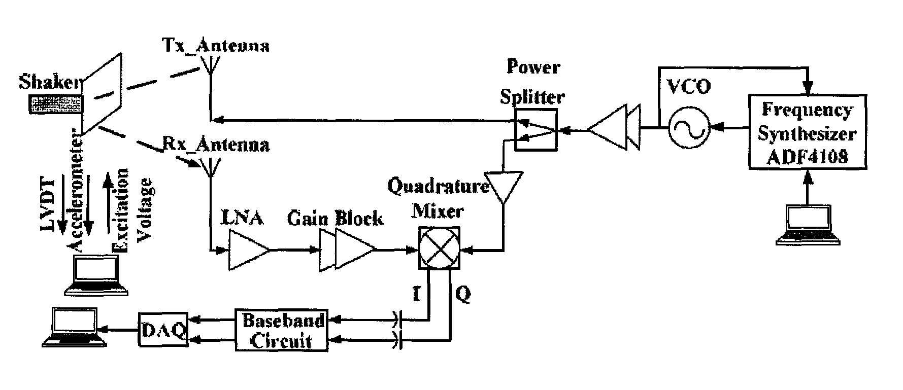
[0007]Embodiments of the subject invention relate to a method and apparatus for providing a RF vibrometer using a wavelength division sensing technique. Embodiments can accurately measure mechanical vibrations having complex patterns that include multiple frequency components, such as triangular waveform or square-wave movement patterns. Embodiments of the method of detection use multiple harmonics in the baseband spectrum generated from nonlinear Doppler phase modulation effect. Embodiments measure the amplitude ratio of multiple harmonic pairs under a fixed carrier frequency to calculate the amplitude of each frequency components of the vibration. An RF vibrometer can be implemented as an indirect-conversion Doppler radar that features quadrature system architecture and utilizes a complex signal demodulation technique to eliminate the residual phase effect. Embodiments of the subject RF vibrometer can be used as an alternative to a laser displacement sensor, due to its advantages of long detection range, workability in low-visibility environment, low cost integration, as well as having comparable detection accuracy with respect to the laser displacement sensor.
[0009]In another embodiment, the nonlinear Doppler phase modulation effect, which would generate harmonics of the movement frequency when the movement amplitude is comparable to the carrier wavelength, allows a method to obtain the pattern of a purely sinusoidal movement. The residual phase effect that will result in the null detection point problem is eliminated by calculating the amplitude ratio between two even order or two odd order frequency components on the baseband spectrum to cancel out the associated residual phase, leaving the ratio determined only by the Bessel function of the movement amplitude. Since the movement frequency can be read directly from the baseband spectrum, after obtaining the value of movement amplitude from the harmonic amplitude ratio, the originally unknown periodic movement can be reconstructed. With the advantage of low sampling rate requirement for measuring high-speed vibrations as well as high accuracy, embodiments of a Doppler radar sensor in accordance with the subject application can provide a low-cost alternative to laser displacement sensors and an alternative to laser Doppler vibrometers in applications of non-contact detection of mechanical vibrations, such as engine or motor vibrations in vehicles.
Problems solved by technology
However, the system could only detect the frequency of movement, not the amplitude.
The microwave Doppler radar in Kim et al. requires high-sampling rate to track the instantaneous velocity of a moving target, and can, therefore, be limited to measure low-velocity movements.
The residual phase problem can limit the radar in Li et al. to measuring sinusoidal movements.
When the movement pattern of the target is a non-sinusoidal periodic waveform, such as multiple sine waves of different frequencies, the detection method of Li el al. may not be effective.
Method used
Image
Click on the blue label to locate the original text in one second.
Reading with bidirectional positioning of images and text.
Examples
experimental verification
[0124]VI. Experimental Verification
[0125]In this section, experimental results of an embodiment of a wavelength division sensing RF vibrometer in accordance with the subject invention is provided. The results are first evaluated through harmonic analysis. The improvement of detection accuracy by using embodiments of the subject method that uses multiple harmonic ratios will then be verified.
[0126]When measuring a vibration that includes three harmonic motions with m1=2.54, m2=1.896, and m3=0.97, as determined above using the curve fitting toolbox of Matlab™, the reference movement pattern of the vibration is:
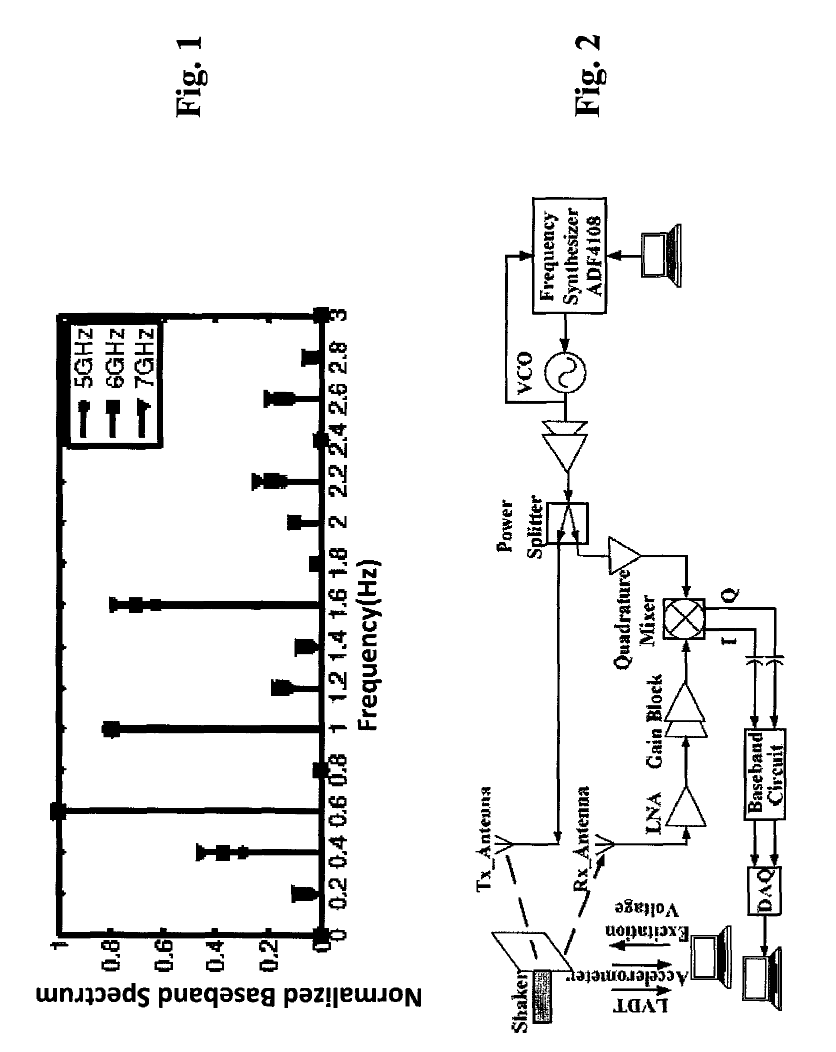
[0127]FIG. 4B is the measured baseband spectrum at 6 GHz. The harmonic amplitude ratio H2 / H10 was chosen with no specific reason. The amplitude of harmonics on the baseband spectrum can be represented as:
PUM
Abstract
Embodiments of the present invention provide a method for non-contact detection techniques of mechanical vibrations utilizing a radio frequency system incorporating multiple carrier wavelengths. The new detection method measures multiple harmonic pairs at a carrier frequency and improves the detection accuracy and reliability by first inspecting the Bessel function coefficient of each harmonic and then determining the harmonic amplitude. The original mechanical vibration can then be reconstructed. Embodiments can be used to realize sensing of complex non-sinusoidal vibrations using a wavelength division sensing technique and allow non-contact detection through walls, smoke, fog or other low visibility environments with the advantage of longer range detection and easy integration at a low cost.
Description
CROSS-REFERENCE TO RELATED APPLICATION[0001]The present application claims the benefit of U.S. Provisional Application Ser. No. 61 / 565,863, filed Dec. 1, 2011, which is hereby incorporated by reference in its entirety, including any figures, tables, or drawings.BACKGROUND OF INVENTION[0002]Microwave and millimeter-wave technologies have been widely used for position sensing, such as described in Stezer et al., “Microwave position sensor with sub millimeter accuracy,” IEEE Trans. Microwave Theory and Techniques, vol. 47, pp. 2621-2624, December 1999. Microwave and millimeter techniques have also been used for precision noise measurement, such as described in Ivanov et al., “Microwave interferometry: Application to precision measurements and noise reduction techniques,” IEEE Trans. Ultrason., Ferroelect., Freq. Contr., vol. 45, pp. 1526-1536, November 1998. Likewise, microwave and millimeter-wave methods have been applied to displacement measurement, such as described in Kim et al., “...
Claims
Application Information
Patent Timeline
Application Date:The date an application was filed.
Publication Date:The date a patent or application was officially published.
First Publication Date:The earliest publication date of a patent with the same application number.
Issue Date:Publication date of the patent grant document.
PCT Entry Date:The Entry date of PCT National Phase.
Estimated Expiry Date:The statutory expiry date of a patent right according to the Patent Law, and it is the longest term of protection that the patent right can achieve without the termination of the patent right due to other reasons(Term extension factor has been taken into account ).
Invalid Date:Actual expiry date is based on effective date or publication date of legal transaction data of invalid patent.

