Anti-reflection coating, optical member having it, and optical equipment comprising such optical member

a technology of anti-reflection coating and optical member, which is applied in the direction of coatings, instruments, optics, etc., can solve the problems of deteriorating optical characteristics, failing to meet the recent demand of visible reflectance of 0.2% in digital camera lenses, and increasing the total amount of light reflected, etc., to achieve excellent reflection-preventing characteristics

Active Publication Date: 2015-12-01
RICOH IMAGING COMPANY
View PDF9 Cites 0 Cited by
  • Summary
  • Abstract
  • Description
  • Claims
  • Application Information

AI Technical Summary

Benefits of technology

[0011]Accordingly, an object of the present invention is to provide an anti-reflection coating having excellent reflection-preventing characteristics in a wavelength range of 390-720 nm wider than the conventional reflection-preventing range of 300 nm.

Problems solved by technology

Increase in the number of lens leads to increase in the total amount of light reflected by lens surfaces, and entering of repeatedly reflected light into a photosensitive surface, causing problems such as flare and ghost, which extremely deteriorate the optical characteristics.
However, this anti-reflection coating has reflectance of at most 0.25% or less in a reflection-preventing band, particularly in a visible band, failing to meet the recent demand of visible reflectance of 0.2% in digital camera lenses.

Method used


Image

  • Anti-reflection coating, optical member having it, and optical equipment comprising such optical member
  • Anti-reflection coating, optical member having it, and optical equipment comprising such optical member
  • Anti-reflection coating, optical member having it, and optical equipment comprising such optical member

Examples


examples 1-1 to 1-13

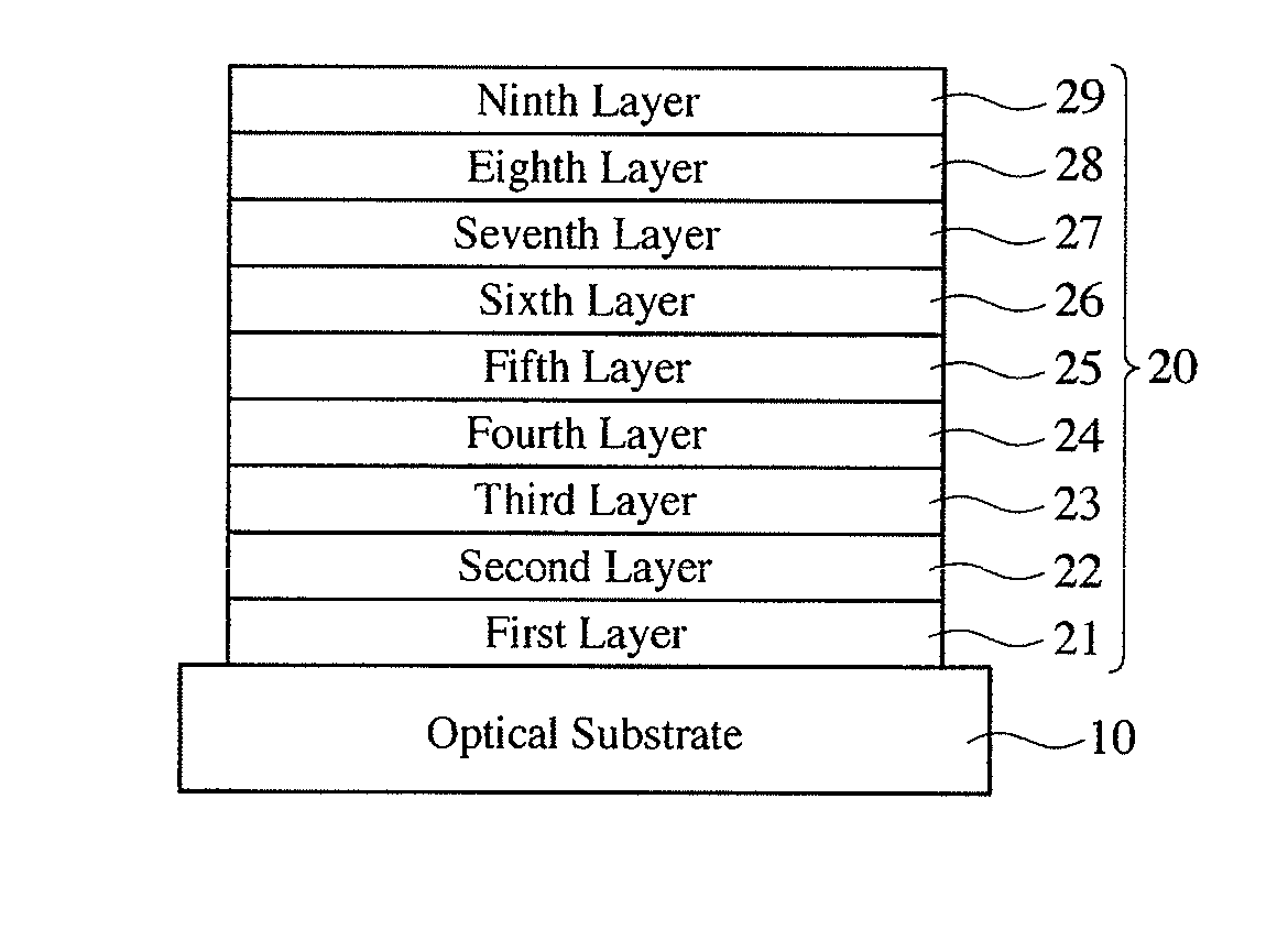
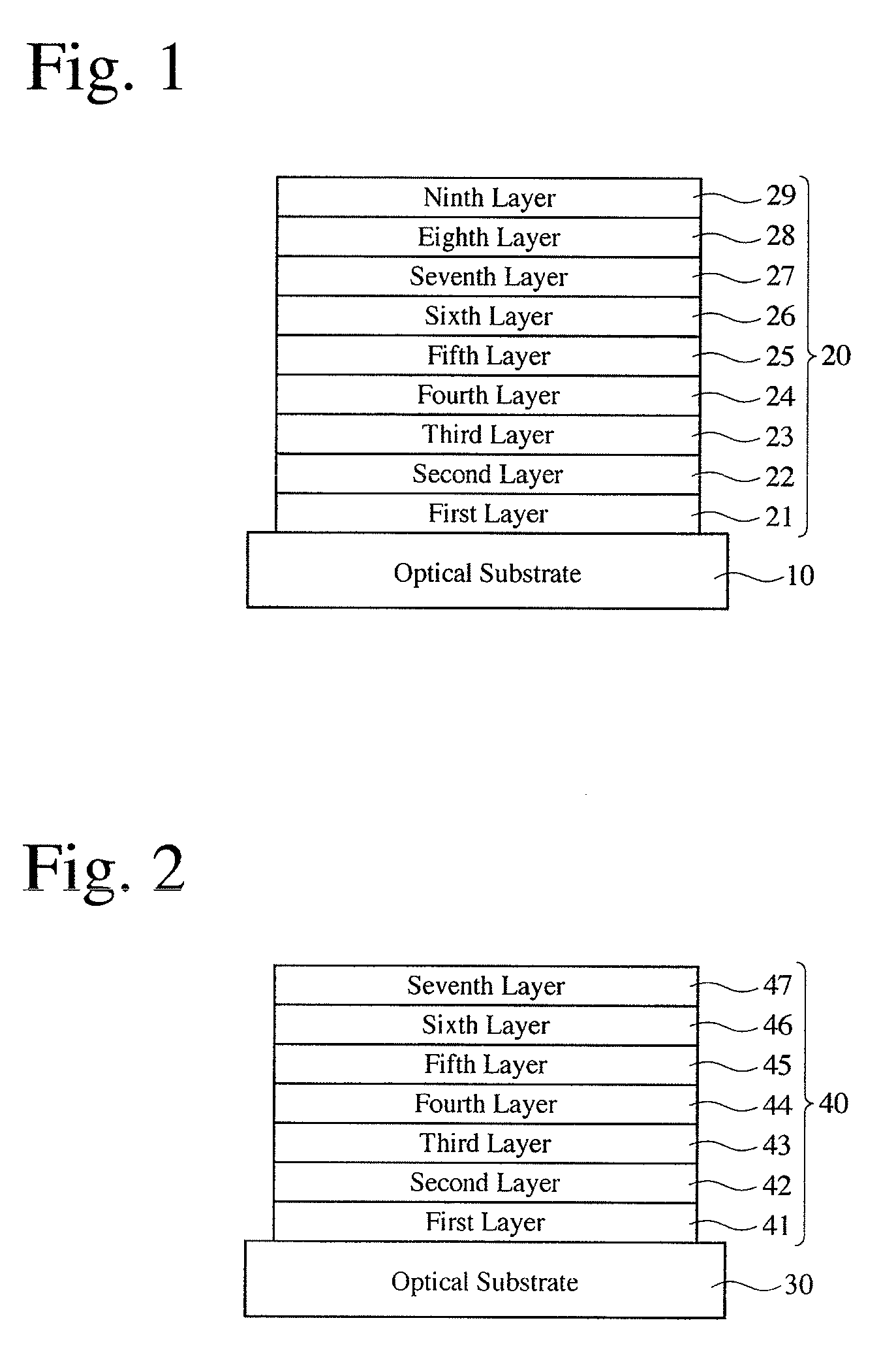
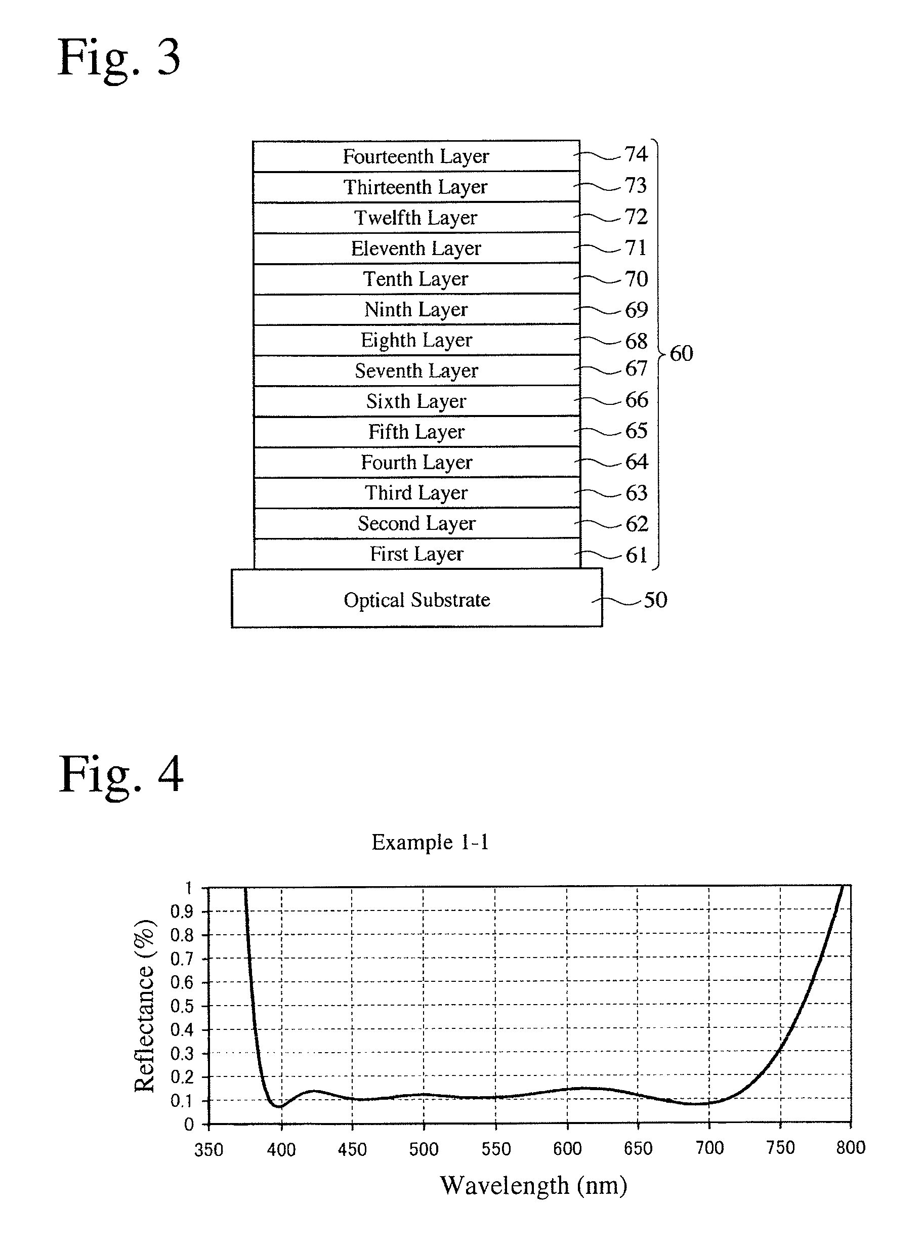
[0103]In each anti-reflection coating 20 according to the first embodiment, which comprised high-refractive-index layers 22, 24, 26 and 28 made of TiO2 having a refractive index of 2.46 to the d-line, intermediate-refractive-index layers 21, 23, 25 and 27 made of SiO2 having a refractive index of 1.48 to the d-line, and a low-refractive-index layer 29 made of MgF2 having a refractive index of 1.39 to the d-line, with air having a refractive index of 1.00 as an incident-side medium, the optimum optical thickness of each layer 21-29 for each substrate 10 was determined by simulation. The material and refractive index of the substrate 10 and the optical thickness of each layer in the anti-reflection coating 20 in each Example 1-1 to 1-13 are shown in Table 1. Using a design wavelength λ0 of 550 nm, the optical thickness of each layer is expressed by number×λ0 in Table 1. The spectral reflectance of each anti-reflection coating 20 of Examples 1-1 to 1-13 to perpendicular incident light ...

examples 2-1 to 2-13

[0105]In each anti-reflection coating 20 according to the first embodiment, which comprised high-refractive-index layers 22, 24, 26 and 28 made of Nb2O5 having a refractive index of 2.31 to the d-line, intermediate-refractive-index layers 21, 23, 25 and 27 made of SiO2 having a refractive index of 1.48 to the d-line, and a low-refractive-index layer 29 made of MgF2 having a refractive index of 1.39 to the d-line, with air having a refractive index of 1.00 as an incident-side medium, the optimum optical thickness of each layer 21-29 for each substrate 10 was calculated by simulation. The material and refractive index of the substrate 10 and the optical thickness of each layer in the anti-reflection coating 20 in each Example 2-1 to 2-13 are shown in Table 2. The spectral reflectance of each anti-reflection coating 20 of Examples 2-1 to 2-13 to perpendicular incident light was calculated by simulation. The calculation results are shown in FIGS. 17-29.

[0106]

TABLE 2SubstrateOptical Thic...

examples 3-1 to 3-13

[0107]In each anti-reflection coating 20 according to the first embodiment, which comprised high-refractive-index layers 22, 24, 26 and 28 made of a mixture of Nb2O5 and HfO2 having a refractive index of 2.21 to the d-line, intermediate-refractive-index layers 21, 23, 25 and 27 made of SiO2 having a refractive index of 1.47 to the d-line, and a low-refractive-index layer 29 made of MgF2 having a refractive index of 1.39 to the d-line, with air having a refractive index of 1.00 as an incident-side medium, the optimum optical thickness of each layer 21-29 for each substrate 10 was calculated by simulation. The material and refractive index of the substrate 10 and the optical thickness of each layer in the anti-reflection coating 20 in Examples 3-1 to 3-13 are shown in Table 3. The spectral reflectance of each anti-reflection coating 20 of Examples 3-1 to 3-13 to perpendicular incident light was calculated by simulation. The calculation results are shown in FIGS. 30-42.

[0108]

TABLE 3Opt...


PUM

PropertyMeasurementUnit
wavelengthaaaaaaaaaa
reflectanceaaaaaaaaaa
refractive indexaaaaaaaaaa

Abstract

A anti-reflection coating comprising first to ninth layers laminated in this order on a substrate for having reflectance of 0.2% or less to light in a visible wavelength range of 390-720 nm, the second, fourth, sixth and eighth layers being high-refractive-index layers formed by high-refractive-index materials having refractive indices of 2.21-2.70 to a helium d-line having a wavelength of 587.56 nm; the first, third, fifth and seventh layers being intermediate-refractive-index layers formed by an intermediate-refractive-index material having a refractive index of 1.40 or more and less than 1.55 to the d-line; and the ninth layer being a low-refractive-index layer formed by a low-refractive-index material having a refractive index of 1.35 or more and less than 1.40 to the d-line.

Description

FIELD OF THE INVENTION[0001]The present invention relates to an anti-reflection coating having low reflectance in a wide wavelength range, an optical member such as a lens, a prism, a filter, etc. having such anti-reflection coating, and an optical equipment such as a TV camera, a video camera, a digital camera, an in-vehicle camera, a microscope, a telescope, etc., comprising such optical member.BACKGROUND OF THE INVENTION[0002]A single-focus lens and a zoom lens widely used for photographing and broadcasting are generally constituted by a large number of lenses, for example, about 10 to 40 lenses.[0003]Increase in the number of lens leads to increase in the total amount of light reflected by lens surfaces, and entering of repeatedly reflected light into a photosensitive surface, causing problems such as flare and ghost, which extremely deteriorate the optical characteristics. Accordingly, these lenses have multi-layer anti-reflection coatings comprising dielectric layers having di...

Claims


Application Information

Patent Timeline
Patent Type & Authority Patents(United States)
IPC IPC(8): G02B27/00G02B1/11G02B1/115
CPCG02B1/115G02B1/11C03C17/3452C03C17/3417C03C2217/734
Inventor FUJII, HIDEOTAKETOMO, HIROKI
Owner RICOH IMAGING COMPANY
Why Eureka
Try Eureka