
Negative stiffness device and method

a negative stiffness and device technology, applied in the field of negative stiffness devices and methods, can solve the problems of physical very difficult and economic prohibitive confinement forces, limited application, and limited technology, and achieve the effect of negative stiffness and negative stiffness

Active Publication Date: 2015-12-08
TAYLOR DEVICES +1
View PDF73 Cites 13 Cited by
  • Summary
  • Abstract
  • Description
  • Claims
  • Application Information

AI Technical Summary

Benefits of technology

The invention introduces a system, device, or method that helps to reduce stiffness during movement, particularly caused by seismic activity. It uses a passive mechanical system that does not require an external power supply. By using a preload force, the invention reduces the demand for a large force that would be required to apply negative stiffness to a structure. This invention can provide seismic protection without adding extra loads on the structure.

Problems solved by technology

Although this approach has shown to be effective, its applications are limited due to its high-power and continuous feedback signal requirements.
To date, however, this technology has been restricted to small mass applications because of the requirement for large forces to develop the necessary low or negative stiffness.
Such large spring forces would provide forces that would be physically very difficult and economically prohibitive to contain.
Negative stiffness concepts have been applied to isolating structures, but the concepts advanced have drawbacks.
However, such systems are complicated, and require high-power and continuous feedback in order to drive the active or semi-active hydraulic devices.
However, this system generates low effective stiffness that emulates the behavior of friction pendulum bearings.
Complications of this system may arise due to the fact that the vertical loads are transferred through an unstable system, which generates constant negative stiffness for all displacement amplitudes.

Method used


Image

  • Negative stiffness device and method
  • Negative stiffness device and method
  • Negative stiffness device and method

Examples


Embodiment Construction

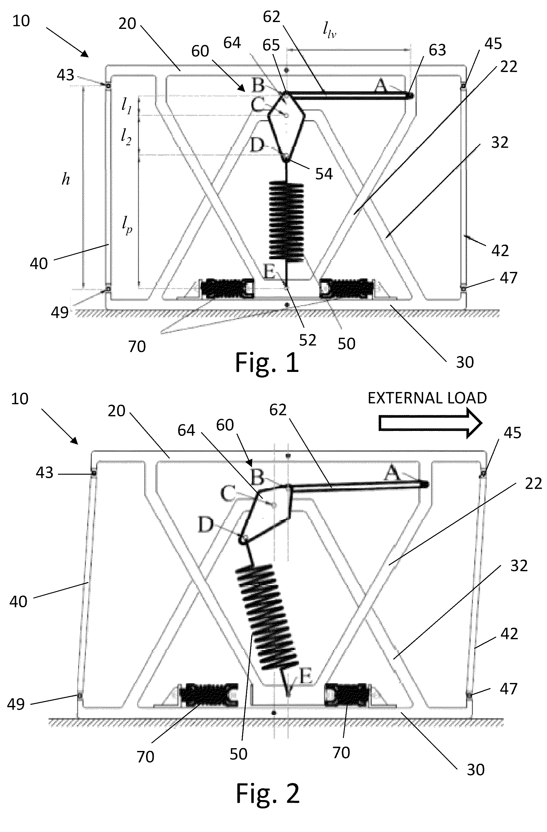
[0048]A schematic of a device 10 according to an embodiment of the present invention is shown in FIG. 1, in a rest state, and shown in FIG. 2, in an engaged state. As shown in FIGS. 1 and 2, the device 10 includes a movement frame 20 and an anchor frame 30. The movement frame 20 has an extension portion 22, which extends in the direction of the anchor frame 30. The anchor frame 30 has an extension portion 32, which extends in the direction of the movement frame 20. In the embodiment shown in FIGS. 1 and 2, the extension portions 22, 32 are chevron braces, but other brace configurations could alternatively be used. Connecting members 40, 42 pivotably connect the anchor frame 30 to the movement frame 20, for example, via hinges 43, 45, 47, 49, such that movement frame 20 is laterally translatable relative to the anchor frame 30. The connecting members 40, 42 can limit the maximum vertical distance h between the movement frame 20 and the anchor frame 30. The embodiment shown in FIGS. 1...


PUM


Abstract

Negative stiffness systems and methods for seismic protection of a structure is described. A system can include a negative stiffness device having a first linkage pivotably connected to an anchor frame at a first pivot point and pivotably connected the movement frame at a second pivot point. The negative stiffness device can include a spring having a first end operably coupled to the anchor frame and a second end operably coupled to a movement frame. In a rest state, the spring can be compressed to exert a preload force to the first linkage and the anchor frame and not displace the first linkage and the movement frame. In an engaged state, the spring can be configured to apply a force to the first linkage such that the movement frame is displaced in a same lateral direction of a seismic load. The spring force can be amplified by the first linkage.

Description

CROSS-REFERENCE TO RELATED APPLICATION[0001]This application claims the benefit of priority to U.S. Provisional Patent Application No. 61 / 840,897 filed Jun. 28, 2013, the disclosure of which is incorporated herein by reference in its entirety.STATEMENT REGARDING FEDERALLY RESEARCH[0002]This invention was made with government support under Grant No.CMMI0830391awarded by National Science Foundation. The government has certain rights in the invention.FIELD OF THE INVENTION[0003]The invention relates to apparatuses for isolating large structures and structural members from seismic forces.BACKGROUND OF THE INVENTION[0004]Systems and devices for improving structural response to earthquakes are based on the principle of seismic isolation, in which energy is generally dissipated by mechanical dissipating devices. In order to prevent damage to maintain structural components, large horizontal displacements must be accommodated. For example, passive systems have been used for this purpose, inc...

Claims


Application Information

Patent Timeline
Patent Type & Authority Patents(United States)
IPC IPC(8): E04B1/98E04H9/02
CPCE04H9/021E04H9/0215
Inventor SARLIS, APOSTOLOS A.CONSTANTINOU, MICHAEL C.LEE, DAVID A.REINHORN, ANDREI M.TAYLOR, DOUGLAS P.
Owner TAYLOR DEVICES
Learn More