
Gravity gradiometer

a gravity gradiometer and gravity field technology, applied in the field ofquadrupole gravity gradiometers, can solve the problems of reducing the sensitivity of the isolation system, no isolation system perfect, etc., and achieve the effect of reducing the sensitivity of the centrifugal force, low response to linear acceleration, and inherent sensitivity to centrifugal for

Inactive Publication Date: 2015-05-26
SRC INC
View PDF24 Cites 1 Cited by
  • Summary
  • Abstract
  • Description
  • Claims
  • Application Information

AI Technical Summary

Benefits of technology

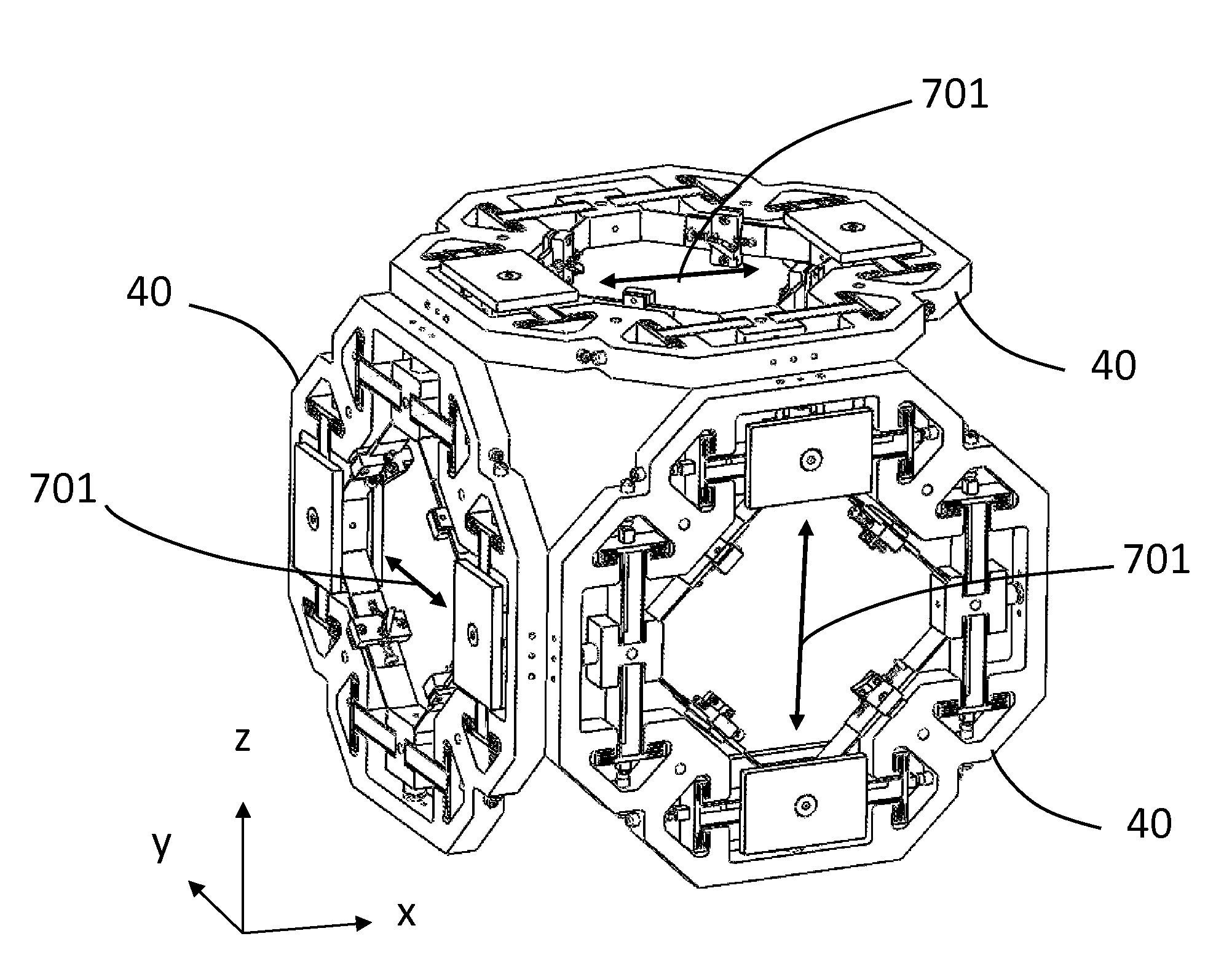
[0014]A gravity gradiometer according to the present invention consists of at least three differential accelerometers that, by their symmetric construction, have low response to linear accelerations. As any gravity gradiometer has inherent sensitivity to centrifugal forces due to non-inertial movement of the carrier platform, the present invention further comprises mounting the gradiometer in a suspension system able to isolate rotations. However, no isolation system is perfect and some rotations are sensed by the instrument causing noise and reducing its sensitivity. The gravity gradiometer according to the present invention also includes at least six angular accelerometers that give it the capability of measuring angular rates by integrating the angular accelerations. Both types of accelerometers are based on a compliant mechanism with very low and adjustable stiffness. This is achieved by using flexures under compressive load that contribute a negative stiffness to the total elastic response of the mechanism. The compliant mechanism is machined out of a single plate of metal by milling and electro-discharge machining. Compared to other construction methods this eliminates uncontrollable friction forces and vibrations, reduces the weight, and eliminates assembly tolerances. Both types of accelerometers are operated in a servo-compensation feedback mode so that at no time is the mechanism far from its equilibrium position. This arrangement ensures linear response over a very large range of forces.

Problems solved by technology

However, no isolation system is perfect and some rotations are sensed by the instrument causing noise and reducing its sensitivity.

Method used


Image

  • Gravity gradiometer
  • Gravity gradiometer
  • Gravity gradiometer

Examples


Embodiment Construction

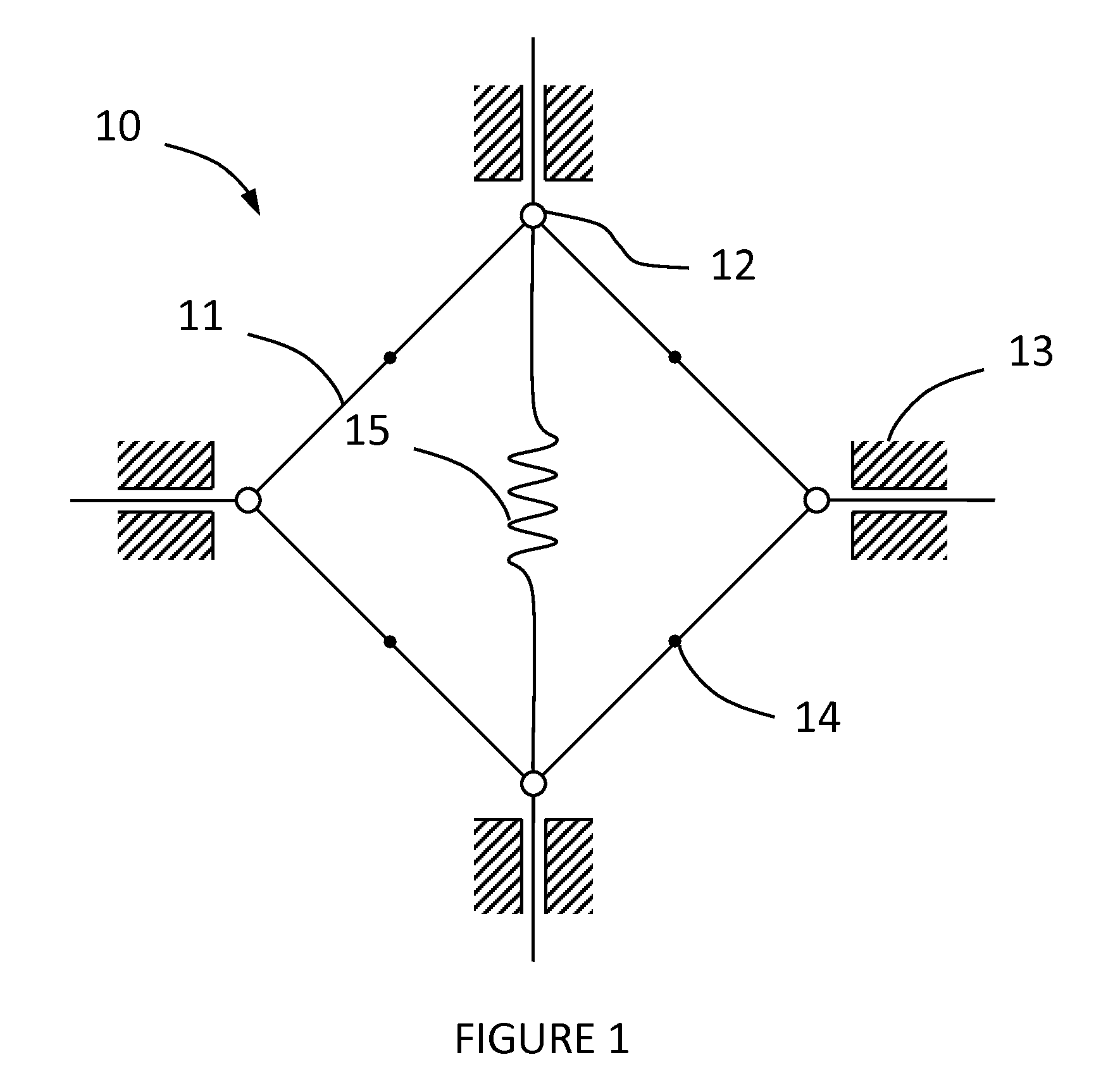
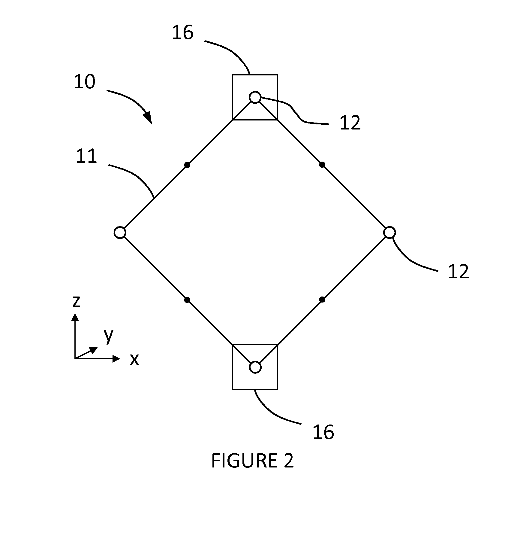
[0028]Referring now to the drawings, wherein like numbers refer to like parts throughout, there is seen in FIG. 1 a differential accelerometer mechanism 10 according to the present that is constrained to move in the plane of the figure. Mechanism 10 includes a linkage comprising four rigid beams 11 of equal length, articulated at a series of nodes 12. Nodes 12 are constrained to move perpendicularly to the symmetry axes of mechanism 10. The constraint is achieved by suspensions, symbolically represented by a series of guides 13, attached to a fixed frame. While nodes 12 execute rectilinear movements, the beam midpoints 14 move along a circle centered at the geometric center of mechanism 10. If an elastic element, such as a spring 15, and a test mass (not shown) are added to mechanism 10, it becomes an accelerometer.

[0029]It is obvious that mechanism 10 has one degree of freedom. Therefore any combination of springs, in any positions, can be represented symbolically by spring 15. Spr...


PUM


Abstract

A gravity gradiometer having at least three differential accelerometers with a low response to linear accelerations and at least six angular accelerometers that give it the capability of measuring angular rates by integrating the angular accelerations. Both types of accelerometers are based on a compliant mechanism with very low and adjustable stiffness that is achieved by using flexures under compressive load that contribute a negative stiffness to the total elastic response of the mechanism. Both types of accelerometers are operated in a servo-compensation feedback mode so that at no time is the mechanism far from its equilibrium position.

Description

BACKGROUND OF THE INVENTION[0001]1. Field of the Invention[0002]The present invention relates to gravity gradiometry and, more particularly, to quadrupole gravity gradiometers.[0003]2. Description of the Related Art[0004]Measuring the gravitational field involves quantifying the gravitational forces acting on test masses. Gravimeter instruments measure the acceleration of gravity and are sensitive to linear accelerations. Doing measurements with an instrument carried by a non-inertial moving platform requires evaluating the inertial forces acting on test masses and subtracting their effect from the measured signal. Also, platform induced forces are many orders of magnitude higher than the variations of acceleration of gravity measured and an appropriate suspension is required on order to reduce such forces to a level that can be handled by the dynamic range of the instrument. For that reason gravity gradiometer instruments are more useful, since they have low sensitivity to linear a...

Claims


Application Information

Patent Timeline
Patent Type & Authority Patents(United States)
IPC IPC(8): G01V7/08G01V7/16G01C19/00G01V7/00
CPCG01V7/00G01V7/16
Inventor DISTASIO, MARCELLO M.NICOLAESCU, ION V.
Owner SRC INC
Learn More