
Computerized tomography (CT) imaging system with multi-slit rotatable collimator

a computerized tomography and collimator technology, applied in the field of imaging systems, can solve the problems of subjecting patients to a higher x-ray dose, and achieve the effect of fast, simple and reliabl

Active Publication Date: 2015-12-08
NEUROLOGICA CORP
View PDF26 Cites 23 Cited by
  • Summary
  • Abstract
  • Description
  • Claims
  • Application Information

AI Technical Summary

Benefits of technology

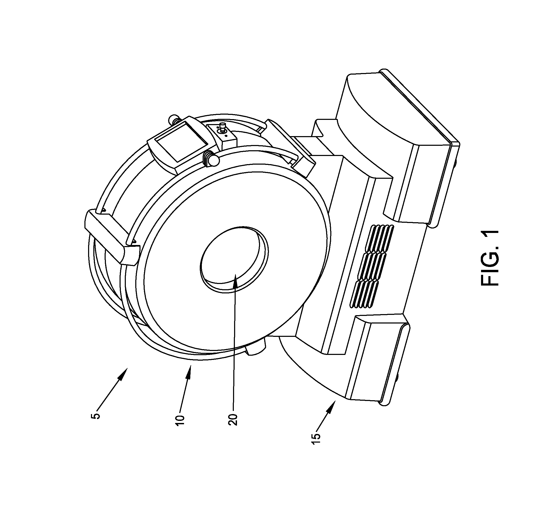
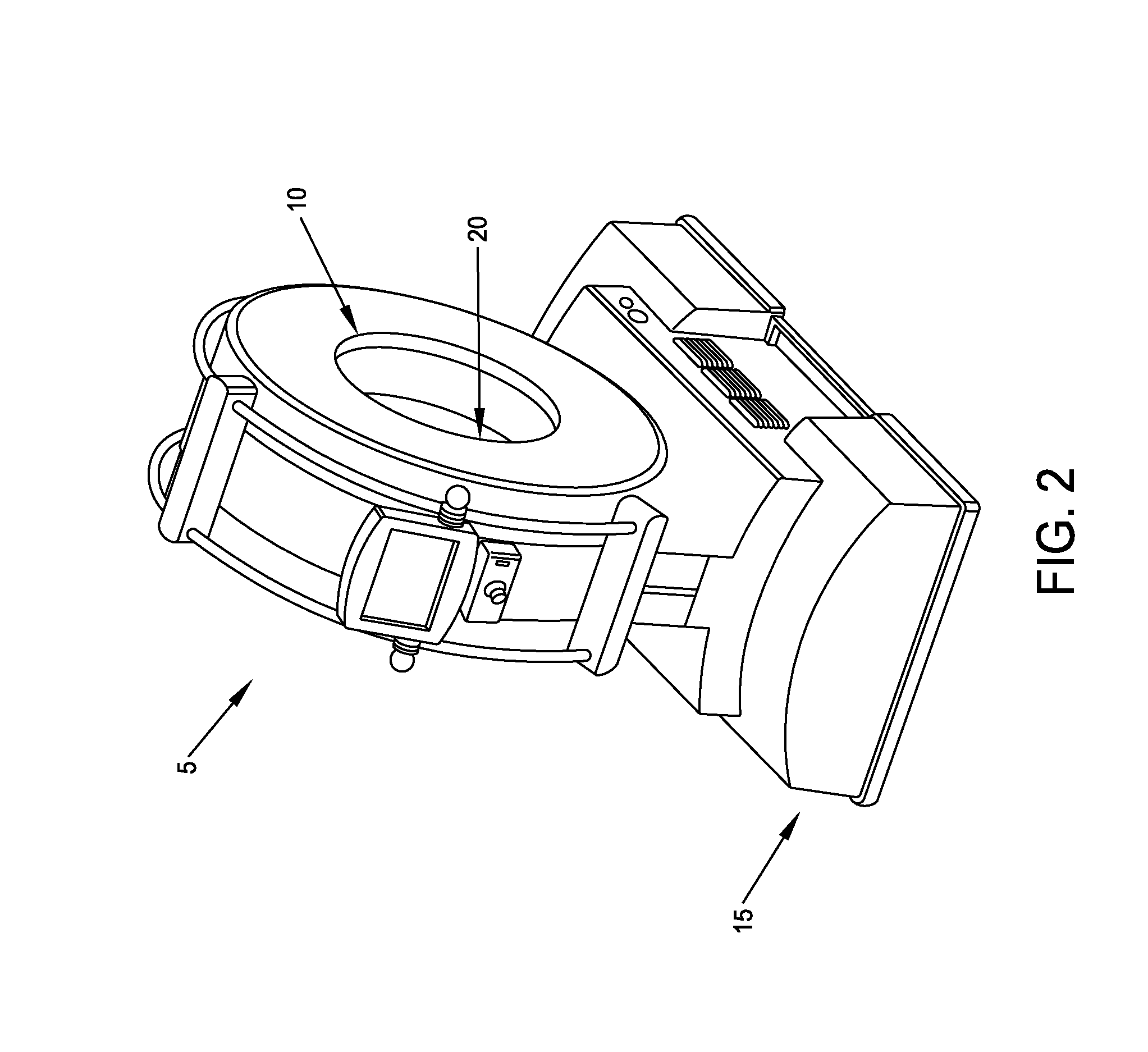
[0015]The present invention provides a fast, simple and reliable way to change collimator slits when the slice count of the scan is to be changed.
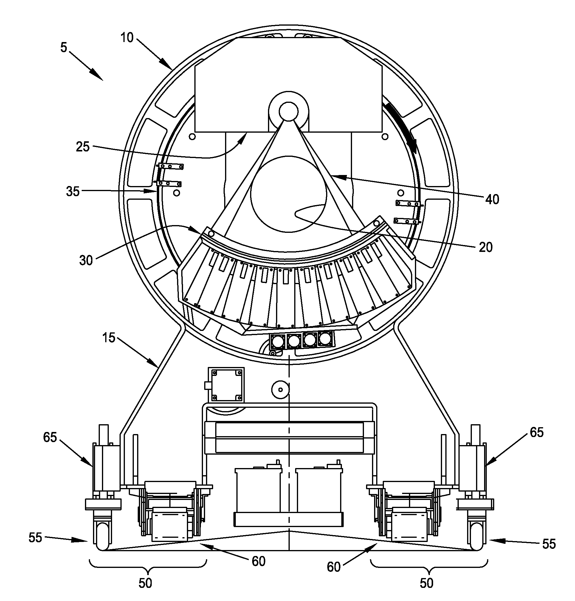
[0016]More particularly, the present invention comprises the provision and use of a novel multi-slit rotatable collimator, wherein each of the slits of the multi-slit rotatable collimator has a different size opening (i.e., each slit has a different width), and wherein the multi-slit collimator is rotated about an axis so as to selectively interpose a given slit between the X-ray tube assembly and the patient, whereby to allow scans of different slice counts to be made. In this way, the present invention provides a fast, simple and reliable way to change collimator slits when the slice count of the scan is to be changed.
[0017]Additionally, the multi-slit rotatable collimator may be rotated about an axis so as to not interpose a given slit between the X-ray tube assembly and the patient, whereby to selectively shield the patient from the X-rays generated by the X-ray tube assembly. In this way, the present invention provides a fast, simple and reliable way to shield the patient from the X-rays generated by the X-ray tube assembly.

Problems solved by technology

In general, scanning with a wider X-ray beam (i.e., a higher slice count) yields faster scanning of a patient than scanning with a narrower X-ray beam (i.e., a lower slice count), but this is generally at the expense of subjecting the patient to a higher X-ray dose.

Method used


Image

  • Computerized tomography (CT) imaging system with multi-slit rotatable collimator
  • Computerized tomography (CT) imaging system with multi-slit rotatable collimator
  • Computerized tomography (CT) imaging system with multi-slit rotatable collimator

Examples


Embodiment Construction

[0047]The present invention provides a fast, simple and reliable way to change collimator slits when the slice count of the scan is to be changed.

[0048]More particularly, the present invention comprises the provision and use of a novel multi-slit rotatable collimator, wherein each of the slits of the multi-slit rotatable collimator has a different size opening (i.e., each slit has a different width), and wherein the multi-slit collimator is rotated about an axis so as to selectively interpose a given slit between the X-ray tube assembly and the patient, whereby to allow scans of different slice counts to be made. In this way, the present invention provides a fast, simple and reliable way to change collimator slits when the slice count of the scan is to be changed.

[0049]Additionally, the multi-slit rotatable collimator may be rotated about an axis so as to not interpose a given slit between the X-ray tube assembly and the patient, whereby to selectively shield the patient from the X-...


PUM


Abstract

Apparatus for collimating an X-ray beam, the apparatus including a multi-slit rotatable collimator including a semi-tubular structure extending coaxially along a longitudinal axis and being formed out of an X-ray impermeable material, with at least two slits formed in the semi-tubular structure, wherein the at least two slits extend parallel to the longitudinal axis of the semi-tubular structure, a mount for rotatably supporting the semi-tubular structure in the path of an X-ray beam, and a drive mechanism for selectively rotating the semi-tubular structure about the longitudinal axis of the semi-tubular structure, whereby to selectively (i) position one slit in the path of the X-ray beam so as to tailor the X-ray beam to the width of that slit, and (ii) position a solid portion of the semi-tubular structure in the path of an X-ray beam so as to block an X-ray beam.

Description

REFERENCE TO PENDING PRIOR PATENT APPLICATION[0001]This patent application claims benefit of prior U.S. Provisional Patent Application Ser. No. 61 / 727,436, filed Nov. 16, 2012 by Andrew Tybinkowski et al. for COMPUTERIZED TOMOGRAPHY (CT) IMAGING SYSTEM WITH MULTI-SLIT ROTATABLE COLLIMATOR, which patent application is hereby incorporated herein by reference.FIELD OF THE INVENTION[0002]This invention relates to imaging systems in general, and more particularly to computerized tomography (CT) imaging systems.BACKGROUND OF THE INVENTION[0003]In many situations, it can be desirable to image the interior of opaque objects. By way of example but not limitation, in the medical field, it can be desirable to image the interior of a patient's body so as to allow viewing of internal body structures without physically penetrating the skin.[0004]Computerized Tomography (CT) has emerged as a key imaging modality in the medical field. CT imaging systems generally operate by directing X-rays into th...

Claims


Application Information

Patent Timeline
Patent Type & Authority Patents(United States)
IPC IPC(8): A61B6/06A61B6/03G21K1/02
CPCG21K1/02A61B6/032A61B6/035A61B6/06
Inventor TYBINKOWSKI, ANDREWNEMIROVSKY, LIDIATYBINKOWSKI, JACK
Owner NEUROLOGICA CORP
Learn More