
Conductive connection structure for secondary batteries

a secondary battery and connection structure technology, applied in the direction of cell lids/covers, cell components, cell component details, etc., can solve the problems of labor and time-consuming and laborious soldering or connecting process, and is not only difficult for anode terminals, and is not easy to smooth assembly, so as to reduce manpower costs

Active Publication Date: 2015-12-08
CHANGS ASCENDING ENTERPRISES CO LTD
View PDF12 Cites 0 Cited by
  • Summary
  • Abstract
  • Description
  • Claims
  • Application Information

AI Technical Summary

Benefits of technology

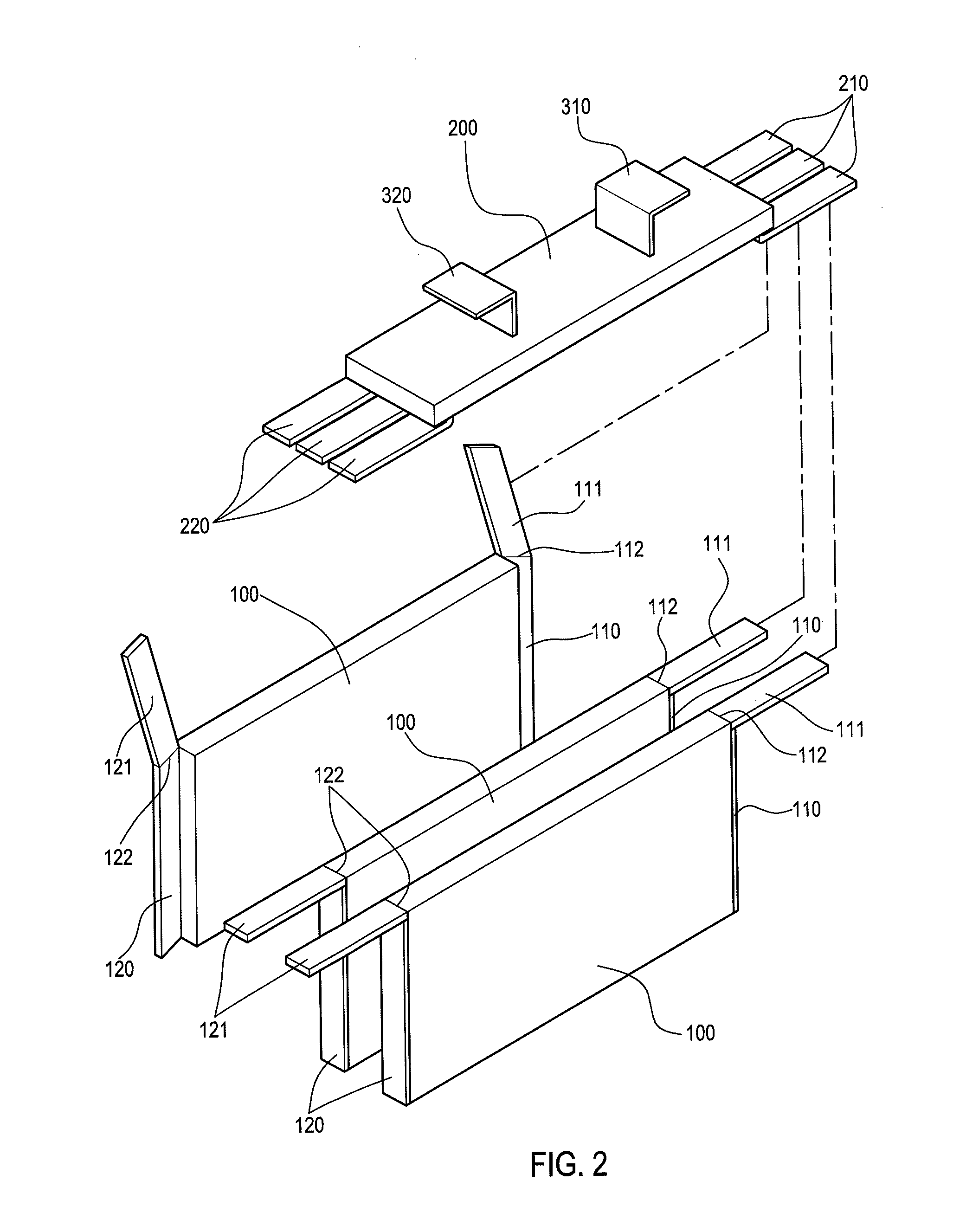
The present invention provides a conductive connection structure for secondary batteries by modifying the design of the connection structure of the battery cells and the two conductive portions under the cover plate. The modified design solves the problem of time and labor consuming for soldering and makes the assembling process easier. The advantages of the invention lie in that the electrical connection between the connecting portions and the conductive portions can be done horizontally and laterally, reducing the time and manpower cost. In addition, the connection method for the connecting portions and the conductive portions provides tighter and more reliable electrical contacts between each of the battery cells and the conductive portions.

Problems solved by technology

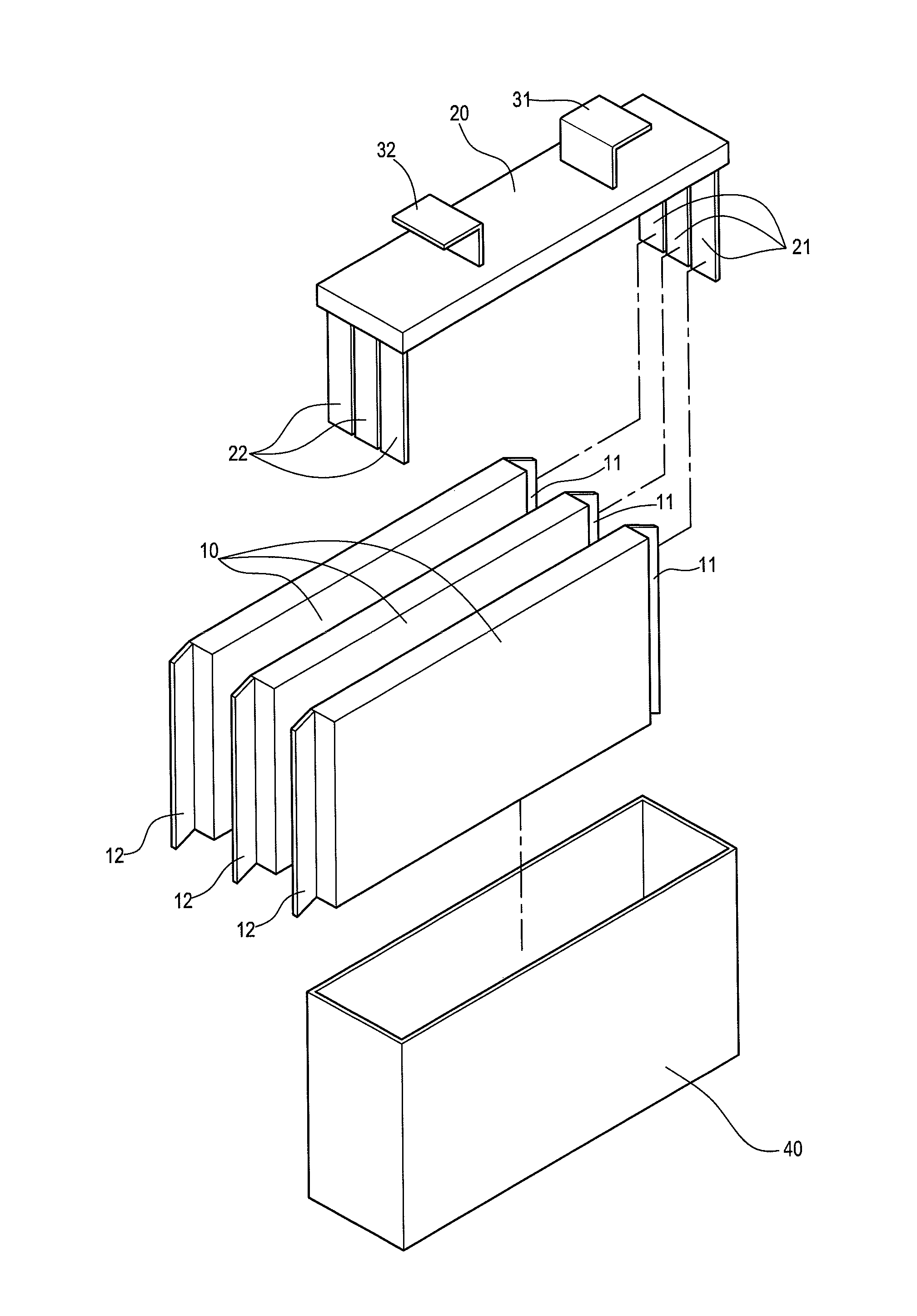
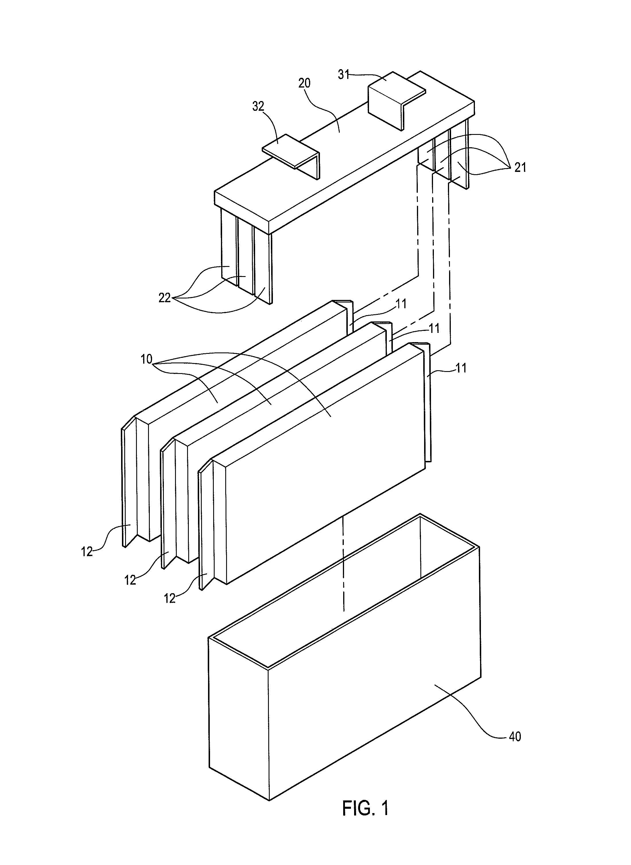
However, the soldering or connecting process is not only labor and time consuming, but it is difficult for the anode terminals 11 / the cathode terminals 12 and the conductive portions 21, 22 to have a tighten electrical connection, which could be rather troublesome for smooth assembling.

Method used


Image

  • Conductive connection structure for secondary batteries
  • Conductive connection structure for secondary batteries
  • Conductive connection structure for secondary batteries

Examples


Embodiment Construction

[0020]The structure and the technical means adopted by the present invention to achieve the above and other objectives can be best understood by referring to the following detailed description of the preferred embodiment and the accompanying drawings, but should not be construed as limitations thereof.

[0021]Referring to FIGS. 2 and 3, they show structures of battery cells and a cover plate of the present, the present invention provides a conductive connection structure for secondary batteries, and a rectangular secondary lithium battery is used as an example. The present technique is mainly applied to secondary batteries in which conductive portions 210, 220 disposed under two lateral sides of a cover plate 200 are conductively connect with at least one battery cell 100 (three battery cells 100 are shown in the figures as an example). Each of the battery cells 100 is composed of an anode layer, an insulating layer and a cathode layer superimposed together. An anode terminal 110 and ...


PUM

PropertyMeasurementUnit
conductiveaaaaaaaaaa
electricallyaaaaaaaaaa
areaaaaaaaaaaa

Abstract

A conductive connection structure for secondary batteries employs conductive portions disposed under two lateral sides of a cover plate to conductively connect to at least one battery cell. The conductive portions disposed under the two lateral sides of the cover plate are bendable, and the conductive portions are bent toward outer sides of the cover plate, so that the conductive portions are disposed horizontally; a connecting portion is extended upward respectively from an anode and a cathode terminals on two lateral sides of each of the battery cells, and the connecting portions and the conductive portions are electrically connected. By modifying the design of the connection structure of the battery cells and the two conductive portions under the cover plate, a time for soldering the battery cells and the conductive portions for conductive connection is reduced, the connection is tighter and more reliable and manpower cost is reduced.

Description

BACKGROUND OF THE INVENTION[0001]1. Field of Invention[0002]The present invention relates to a conductive connection structure for secondary batteries and more particularly to a connection structure for battery cells and an anode terminal or a cathode terminal on a battery cover plate inside a secondary battery.[0003]2. Related Art[0004]Because of breakthroughs in materials technology for lithium batteries, secondary batteries have become a power supplies source (e.g. lithium iron phosphate oxide) for devices which require large electricity consumption such as electric bikes and electric wheelchairs. The power storage quantity and power supply quantity of non-aqueous electrolytic secondary lithium batteries are larger than those of conventional lithium battery.[0005]Referring to FIG. 1, it shows a conventional high capacity rectangular secondary battery, which comprises a plurality of battery cells 10 (three battery cells 10 are shown in the figure for an example). Each of the batte...

Claims


Application Information

Patent Timeline
Patent Type & Authority Patents(United States)
IPC IPC(8): H01M2/22H01M2/30H01M2/20H01M2/26H01M50/528H01M50/147H01M50/533H01M50/536H01M50/55
CPCH01M2/206H01M2/266H01M2/22H01M2/30Y02E60/10H01M50/528H01M50/147H01M50/55H01M50/536H01M50/533H01M50/15
Inventor CHANGLIN, TING-KENG
Owner CHANGS ASCENDING ENTERPRISES CO LTD
Learn More