Femoral head prosthesis

a femoral head and prosthesis technology, applied in the field of femoral head prosthesis, can solve the problems of large femoral head, frequent groin pain, intermittent groin pain, etc., and achieve the effect of removing sharp edges

Active Publication Date: 2015-12-15
MCMINN DEREK JAMES WALLACE
View PDF18 Cites 2 Cited by
  • Summary
  • Abstract
  • Description
  • Claims
  • Application Information

AI Technical Summary

Benefits of technology

[0013]Embodiments of the first two aspects of the invention therefore provide a femoral head (either alone or integral with a femoral stem) having a low anterior / antero-inferior profile. The femoral head is therefore asymmetrical in an anterior to posterior direction. The Applicant believes that such a design may help to eliminate the groin pain encountered with prior art components since he believes such pain to be caused by the sharp and bulky depending edge of those femoral heads interfering with the excursion of the psoas tendon anteriorly and / or antero-inferiorly. By reducing the extent of the femoral head anteriorly and / or antero-inferiorly, in accordance with the present invention, it is therefore hoped that the advantages of using large femoral heads can be realised without an associated risk of groin pain.
[0015]It will be noted that in a posterior direction, the femoral head may protrude to the same (or a similar) degree as in a traditional femoral head design. This is important because, due to femoral neck anteversion and acetabular component anteversion, a more complete femoral head prosthesis is required posteriorly for satisfactory articulation between the posterior head and acetabular components. Thus, the present invention allows for reduced bulk in regions where it is not essential whilst maintaining material in other regions where it is required for satisfactory load transfer and range of movement.
[0017]The second edge may comprise an arcuate portion having a radius of curvature which is less than that of the articulating surface. The second edge may comprise an outer end wherein a tangent to the arcuate portion is perpendicular to the anterior-posterior plane and / or may comprise an inner end wherein a tangent to the arcuate portion is parallel to the anterior-posterior plane. This feature therefore eliminates the sharp edge commonly provided on a femoral head prosthesis in an anterior and / or antero-inferior location.
[0021]The femoral head may comprise only a single internal recess which is configured for receipt of a sleeve and / or a femoral neck. The recess may be of an inwardly tapering frusto-conical shape. The recess may terminate at an inner end of the second edge and an inner end of the first edge. It will therefore be understood that the recess of the present invention may have an outer diameter which is proportionally larger than that of prior art components where the recess is provided within a separate channel which is set back from the depending skirt of the femoral head. This feature therefore not only helps to reduce the overall bulk and weight of the component but also eliminates the need for sharp edges.
[0027]The sleeve may be configured such that, when inserted into the internal recess of the femoral head, a base of the sleeve is level with an inner end of the second edge. This further helps to eliminate sharp edges in the design, which could catch on the psoas tendon.

Problems solved by technology

However, a disadvantage of the use of large femoral heads is intermittent groin pain, thought to be due to interference with a free excursion of a psoas tendon.
It has, however, been found that groin pain is commonly associated with the use of such hollowed-out femoral heads, like that illustrated in FIG. 2.

Method used


Image

  • Femoral head prosthesis
  • Femoral head prosthesis
  • Femoral head prosthesis

Examples


Embodiment Construction

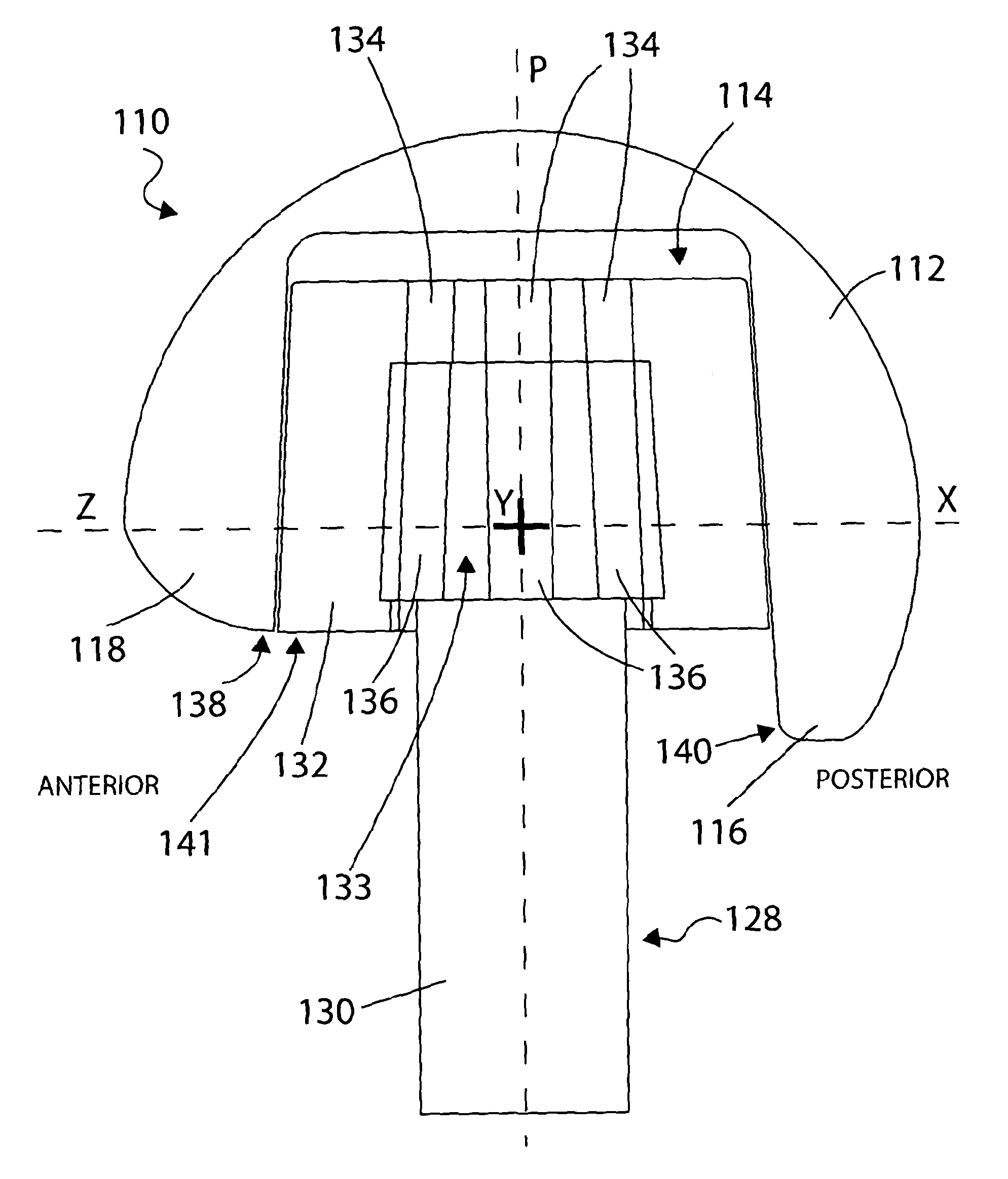
[0038]With reference to FIGS. 3A and 3B, there is illustrated a metal femoral head 110 according to a first embodiment of the present invention. The femoral head 110 comprises an articulating surface 112 which is more than hemi-spherical and an internal recess 114 having a longitudinal axis defining a pole P of the articulating surface 112. A first edge 116 is provided which constitutes a posterior edge in use, and a second edge 118 is provided which constitutes an anterior edge and an antero-inferior edge in use. Importantly, the first edge 116 is further from the pole P than the second edge 118.

[0039]The first and second edges 116, 118 are joined on both sides of the articulating surface 112, by an intermediate edge 120. As illustrated, the intermediate edges 120 provide a smoothly curved step from the lower first edge 116 to the higher second edge 118.

[0040]It will be noted that the femoral head 110 is symmetrical about a first plane which is collinear with the pole P and which e...


PUM


Abstract

A femoral head prosthesis (110) comprises an articulating surface (112) which is more than hemi-spherical; an internal recess (114) having a longitudinal axis defining a pole P of the articulating surface (112), the longitudinal axis passing through the center of curvature of the articulating surface (112); a first edge (116) which constitutes a posterior edge in use, and a second edge (118) which constitutes an anterior edge and / or an antero-inferior edge in use. The first edge (116) is further from the pole P than the second edge (118). Also provided is a femoral prosthesis comprising a femoral head, and a femoral implant comprising a femoral stem and a femoral head. The prostheses and implants of the invention find use in total hip replacements.

Description

RELATED APPLICATIONS[0001]This application is a U.S. National Phase Application of PCT / GB2012 / 051675, filed Jul. 13, 2012, which claims priority to and the benefit of United Kingdom Patent Application No. 1112287.6, filed on Jul. 15, 2011, and United Kingdom Patent Application No. 1205877.2, filed Apr. 2, 2012, all of which are incorporated herein by reference.FIELD OF THE INVENTION[0002]The present invention relates to a femoral head prosthesis. Particularly, but not exclusively, the invention relates to a large femoral head prosthesis for use in total hip replacements.BACKGROUND TO THE INVENTION[0003]Large femoral heads are increasingly being used in total hip replacement procedures. Some advantages of using a large femoral head are a reduced dislocation rate and reduced impingement between a femoral neck of a hip replacement prosthesis and a corresponding acetabular cup edge.[0004]However, a disadvantage of the use of large femoral heads is intermittent groin pain, thought to be ...

Claims


Application Information

Patent Timeline
Patent Type & Authority Patents(United States)
IPC IPC(8): A61F2/36A61F2/30
CPCA61F2/3609A61F2/3607A61F2002/30112A61F2002/30332A61F2002/30367A61F2002/30474A61F2002/30604A61F2002/30688
Inventor MCMINN, DEREK JAMES WALLACE
Owner MCMINN DEREK JAMES WALLACE
Why Eureka
Try Eureka