Nock bushing

a nock and bushing technology, applied in the direction of arrows, etc., can solve the problems of increasing the life of the arrow shaft, and achieve the effect of reducing the weight and lightening the weight of the nock bushing

Active Publication Date: 2015-12-15
HUANG DORGE O
View PDF9 Cites 3 Cited by
  • Summary
  • Abstract
  • Description
  • Claims
  • Application Information

AI Technical Summary

Benefits of technology

[0007]The present invention provides an improved nock bushing, which includes a plurality of lightening openings to decrease weight thereof. A bushing hole is formed in a nock end of an arrow shaft to receive a nock bushing. The improved nock bushing (nock bushing) preferably includes a non-round body and a stop flange. The non-round body preferably has a square shape, but could have a triangular, hexagon, or any other suitable shape. A nock hole is formed through at least substantially all of a length of the non-round body to receive a projection from an arrow nock. A plurality of lightening openings are formed through the non-round body to lighten the weight of the nock bushing.
[0008]The stop flange extends from one end of the non-round body to prevent the nock bushing from being inserted too far into an arrow shaft bushing hole. A distance across the largest cross-section dimension of the non-round body is preferably 1-1.5 percent greater than the diameter of the arrow shaft bushing hole, but other percentages may also be used. An undercut is preferably formed under the stop flange, adjacent the non-round body. The undercut has the unexpected result of increasing the life of an arrow shaft.
[0010]Accordingly, it is an object of the present invention to provide a nock bushing, which does not require adhesive, cement, glue or the like to retain thereof in the end of an arrow shaft.
[0011]It is a further object of the present invention to provide a nock bushing, which ensures concentricity of thereof relative to an arrow shaft.
[0012]Finally, it is another object of the present invention to provide a nock bushing, which includes a plurality of lightening openings to decrease weight thereof.

Problems solved by technology

The undercut has the unexpected result of increasing the life of an arrow shaft.

Method used


Image

  • Nock bushing
  • Nock bushing
  • Nock bushing

Examples


Embodiment Construction

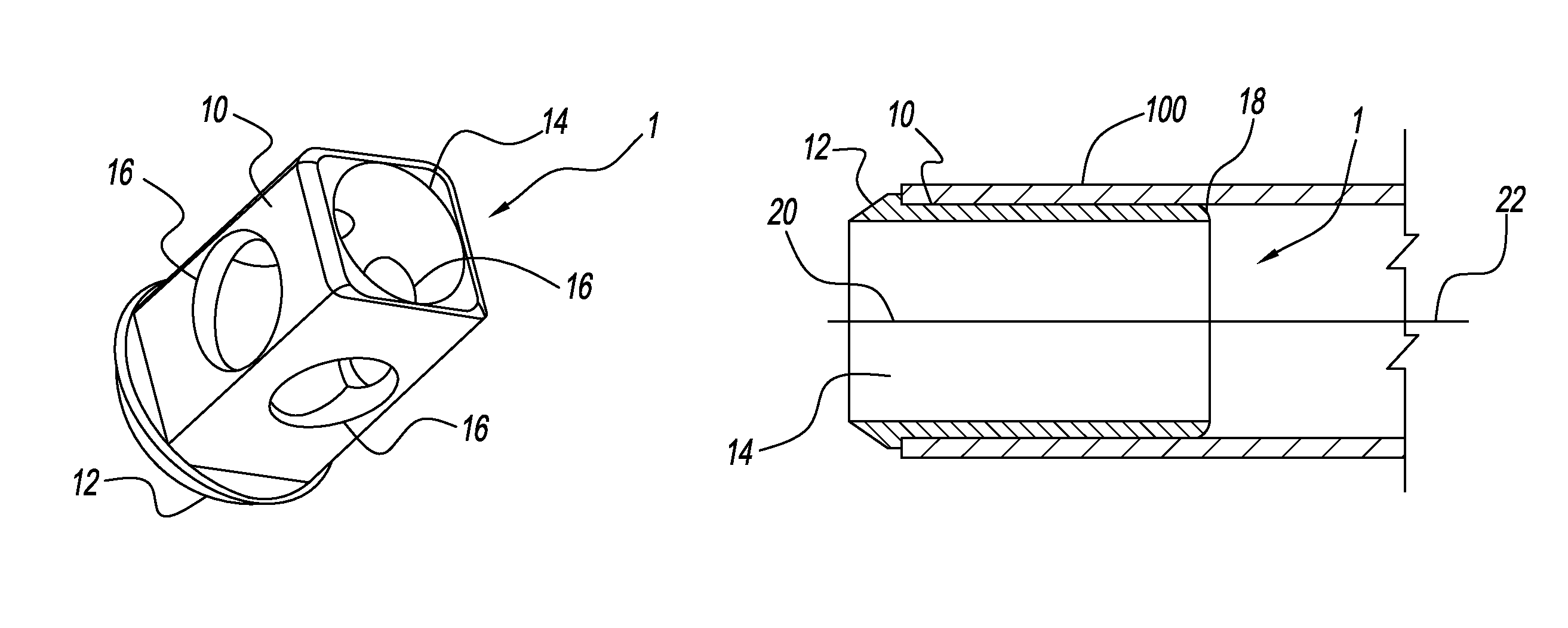
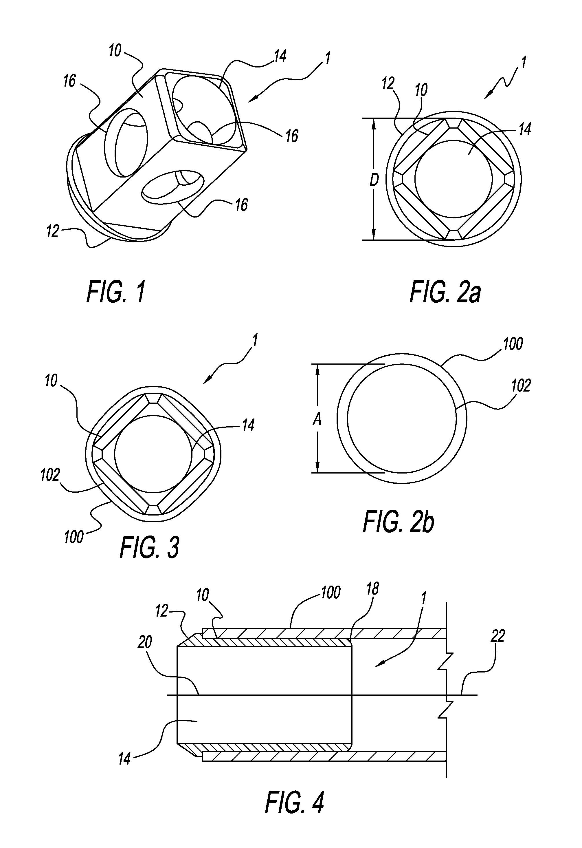
[0021]With reference now to the drawings, and particularly to FIG. 1, there is shown a perspective view of a nock bushing 1. The nock bushing 1 preferably includes a non-round body 10 and a stop flange 12. The non-round body 10 preferably has a square shape, but could have a triangular, hexagon, or any other suitable shape. A nock hole 14 is formed through at least substantially all of a length of the non-round body 10 to receive a projection from an arrow nock. A plurality of lightening openings 16 are formed through the non-round body to lighten the weight of the nock bushing 1.

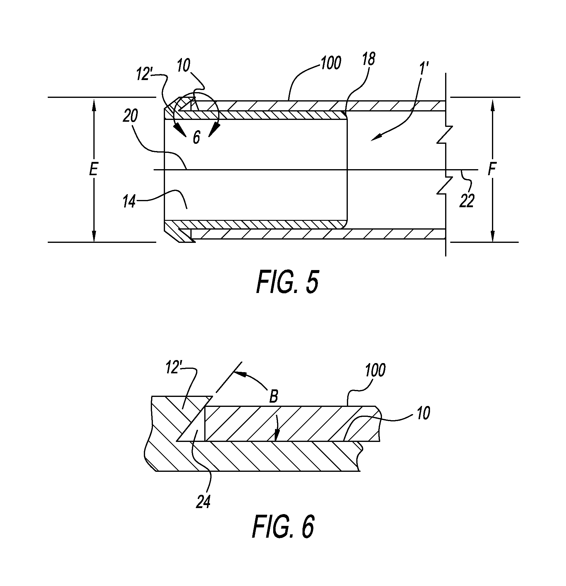
[0022]The stop flange 12 extends from one end of the non-round body 10 to prevent the nock bushing 1 from being inserted too far into a bushing hole 102 of an arrow shaft 100. The other end of the non-round body 10 is preferably broken with a radius 18, chamfer or the like to facilitate insertion into the bushing hole 102. A measurement across the largest cross-section dimension “D” of the non-round body 10...


PUM


Abstract

An improved nock bushing preferably includes a bushing body and a stop flange. The bushing body preferably has a non-round body. An undercut is preferably formed under the stop flange. A nock hole is formed through at least substantially all of a length of the non-round body to receive a projection from an arrow nock. A plurality of lightening openings are preferably formed through the bushing body. The stop flange extends from one end of the bushing body. A distance across the largest cross-section dimension of the bushing body is preferably greater than a diameter of a bushing hole in an arrow shaft. In use, the non-round body is inserted into a nock end of an arrow shaft, which flexes the nock end. The arrow shaft will want to return back to its original round shape and thus applies force to an outer surface of the bushing body.

Description

CROSS-REFERENCES TO RELATED APPLICATIONS[0001]This is a continuation-in-part patent application taking priority from patent application Ser. No. 13 / 863,440 filed on Apr. 16, 2013.BACKGROUND OF THE INVENTION[0002]1. Field of the Invention[0003]The present invention relates generally to archery arrows and more specifically to an improved nock bushing, which provides improved retention of a nock in the end of an arrow shaft.[0004]2. Discussion of the Prior Art[0005]A nock is retained on one end of a nock bushing and the other end of nock bushing is inserted into a nock end of an arrow shaft. Most arrow shafts are fabricated from carbon fiber material. The nock bushing is fabricated from an incompressible metal, such aluminum. Carbon fiber material is nearly incompressible. Retention of a nock bushing in the arrow shaft typically requires the use of an adhesive, cement, glue or the like to secure the nock bushing in the arrow shaft bushing hole. The use of adhesive, cement, glue or the ...

Claims


Application Information

Patent Timeline
Patent Type & Authority Patents(United States)
IPC IPC(8): F42B6/06
CPCF42B6/06
Inventor HUANG, DORGE O.
Owner HUANG DORGE O
Why Eureka
Try Eureka