
Using surfaces with printed patterns for image and data processing

a surface and pattern technology, applied in the field of image processing and pattern recognition, can solve the problems of perspective distortion, background effects, and bending toward notebook edges, so as to facilitate the detection of item orientation and eliminate grid curvature and/or distortion

Active Publication Date: 2015-12-15
EVERNOTE
View PDF24 Cites 6 Cited by
  • Summary
  • Abstract
  • Description
  • Claims
  • Application Information

AI Technical Summary

Benefits of technology

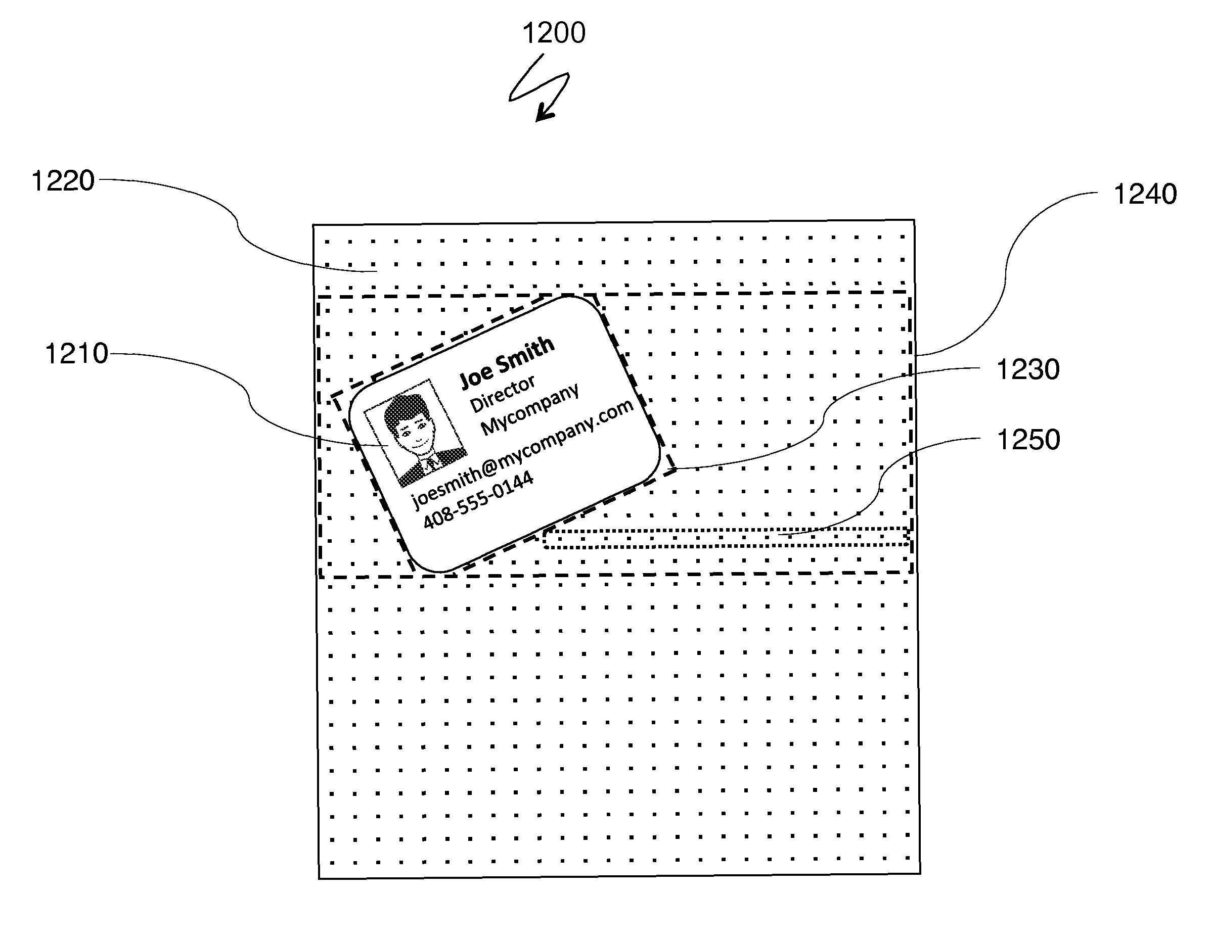
[0010]According to the system described herein, adjusting data for photographed images includes detecting a reference image in the data, where the reference image contains a detectable uniformity and adjusting the data according to the reference image. The reference image may be a uniform grid pattern of dots preprinted on paper. A paper type may be determined prior to adjusting the data according to the reference image. The paper type may be determined according to spacing and / or patterns of the dots, and / or layout of page areas covered with dots. Adjusting the data may include removing effects corresponding to a folded corner, a removed corner, an obstructed corner, lens flare spots, and / or a shadow. Positional coordinates of the data may be adjusted by normalizing the grid through a non-linear transformation that eliminates curvature of the grid and / or distortions based on perspective. Adjusting the data may include detecting page boundaries. The photographed image may be handwritten notes on the preprinted paper that are photographed using a mobile phone. Color and brightness correction may be performed by comparing color and brightness of the paper and dots with ideal brightness values for the paper and dots. Ideal brightness of the ink may be determined through calculations based on brightness values of the paper and the dots for the particular paper type. Adjusting data for photographed images may also include removing the grid pattern in connection with adjusting the data. The reference image may be a background pattern provided on an item. The disposition of the background pattern may facilitate detecting orientation of the item. The reference image may have a pre-defined color that is used for color correction. The reference image may be an image of a tray. The tray may be oval or rectangular and may include dividers. Detecting a reference image may include a reverse image search and content-based image retrieval techniques. A content-based image retrieval technique may be selected from the group consisting of: TinEye, Imprezzeo, and Macroglossa.
[0011]According further to the system described herein, computer software, provided in a non-transitory computer-readable medium, adjusts data for photographed images. The software includes executable code that detects a reference image in the data, where the reference image contains a detectable uniformity and executable code that adjusts the data according to the reference image. The reference image may be a uniform grid pattern of dots preprinted on paper. A paper type may be determined prior to adjusting the data according to the reference image. The paper type may be determined according to spacing and / or patterns of the dots, and / or layout of page areas covered with dots. Adjusting the data may include removing effects corresponding to a folded corner, a removed corner, an obstructed corner, lens flare spots, and / or a shadow. Positional coordinates of the data may be adjusted by normalizing the grid through a non-linear transformation that eliminates curvature of the grid and / or distortions based on perspective. Adjusting the data may include detecting page boundaries. The photographed image may be handwritten notes on the preprinted paper that are photographed using a mobile phone. Color and brightness correction may be performed by comparing color and brightness of the paper and dots with ideal brightness values for the paper and dots. Ideal brightness of the ink may be determined through calculations based on brightness values of the paper and the dots for the particular paper type. The software may also include executable code that removes the grid pattern in connection with adjusting the data. The reference image may be a background pattern provided on an item. The disposition of the background pattern may facilitate detecting orientation of the item. The reference image may have a pre-defined color that is used for color correction. The reference image may be an image of a tray. The tray may be oval or rectangular and may include dividers. Detecting a reference image may include a reverse image search and content-based image retrieval techniques. A content-based image retrieval technique may be selected from the group consisting of: TinEye, Imprezzeo, and Macroglossa. The software may be pre-loaded with a device, installed from an app store, or downloaded from a location of a network operator.

Problems solved by technology

Notwithstanding significant advances in smartphone camera quality and processing power of mobile devices, capabilities and scope of online services, and their extended document and image processing features, smartphone scanning still faces significant challenges for both categories of document and barcode scanning.
In some cases, obtaining quality images of handwritten pages from a camera phone and other photos is a difficult task.
Photographs of handwritten pages are subject to variable lighting conditions, perspective distortion, background effects, bending toward notebook edges, etc.
Such approaches make page identification results vulnerable to occasional reflections and shadows, interference with unrelated objects that may shield portions of photographed pages, etc.
These actions may be reoccurring from note to note and may be easily forgotten if not memorized instantly.
However, existing paper based note-taking systems lack simple, easily recognizable and convenient means of indicating actions that can be instantly converted into the digital form identifiable on smartphone photographs of notebook pages.
Analogously, the usage of QR codes and other rasterized identifiers is not without problems.
One disadvantage of such marks lays in their conflict with the aesthetics of product design.
For many small-size goods carrying aesthetical functions, the presence of a relatively large black-and-white square patch might be a considerable design problem.
For example, an online marketing guide to QR codes repeatedly warns against an inappropriate use of QR codes on promotional items: “Putting the code on the front makes the t-shirt unattractive .
Another potential issue with processing matrix barcodes is that, in spite of generally reliable error correction codes incorporated into such identifiers, their recognition completely depends on the location of characteristic elements within the codes, such as the bullseye cropping marks at the angles of a QR code or the black L-shaped finder pattern border and the alternate timing pattern border in a Data Matrix barcode.
In a non-commercial photographing environment, these elements may be easily obstructed and may be quite sensitive to lighting conditions, which creates an increased risk of losing the recognizable codes which are present on the photo but remain unidentified by the software.
It also takes time for a user to locate and target matrix barcodes with a phone camera, which doesn't align well with other photographing activities where the aesthetical aspect is important and where image processing tasks are involved.

Method used


Image

  • Using surfaces with printed patterns for image and data processing
  • Using surfaces with printed patterns for image and data processing
  • Using surfaces with printed patterns for image and data processing

Examples


Embodiment Construction

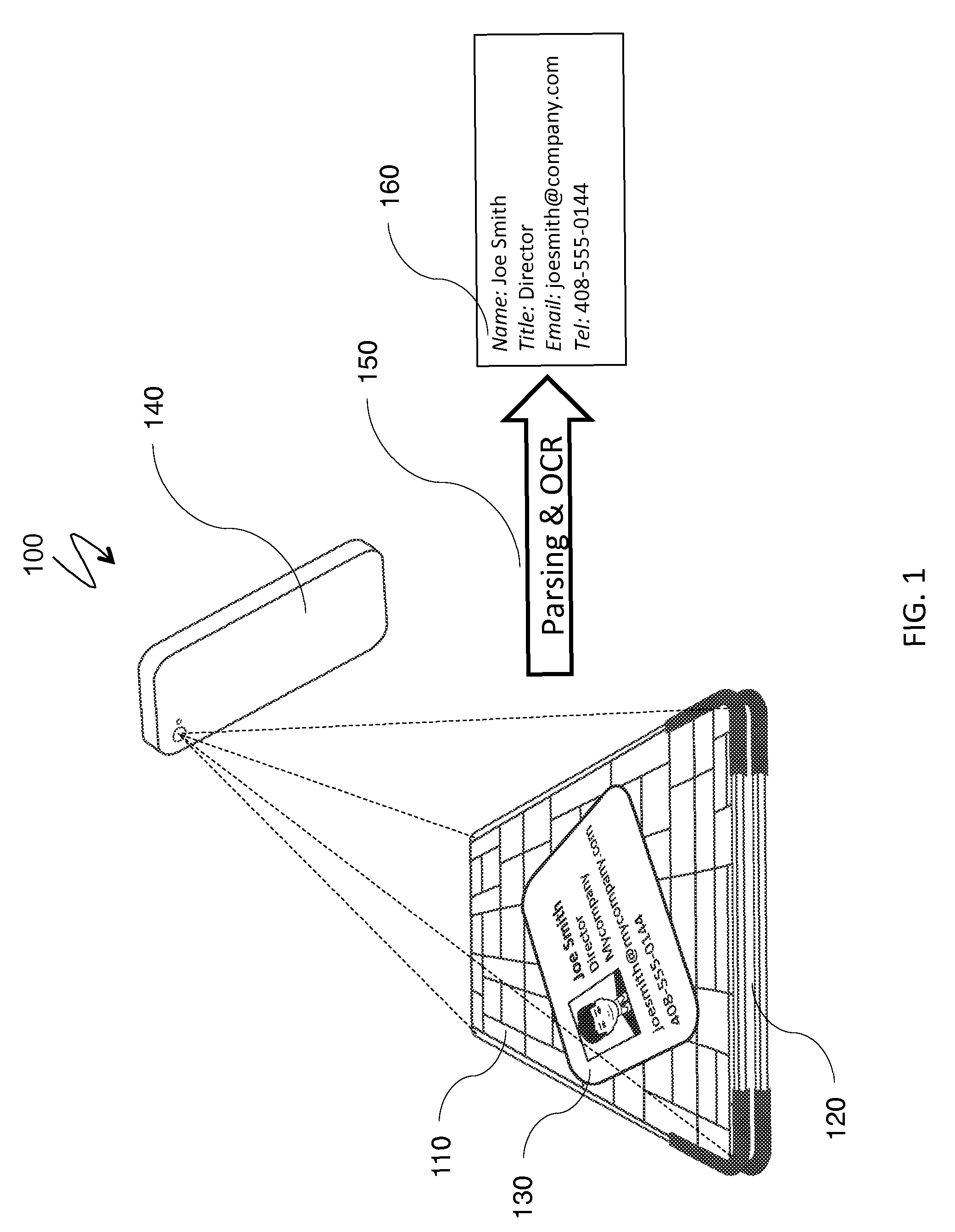
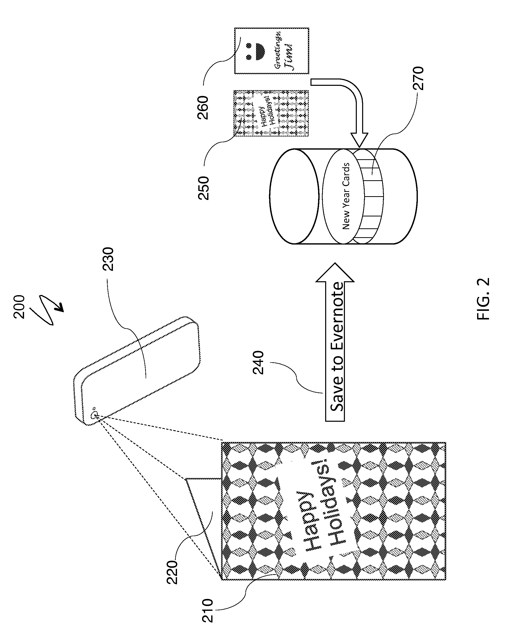
[0065]The system described herein provides a mechanism for creating, storing, producing, identifying and utilizing smart patterns, smart surfaces, smart fabrics, smart notebooks with simple pre-printed patterns, and smart stickers. The system provides different techniques for assigning tasks to smart patterns, processing photographs of objects with smart fabrics and performing activities associated with smart stickers.

[0066]FIG. 1 is a schematic illustration 100 of smart fabrics in conjunction with a business card holder and a task of processing photographs of business cards. A smart pattern 110, in this case a domino tiling on a monochromatic or a multicolor background, represents smart fabrics, or a smart surface of a business card holder 120. A business card 130 is placed on a surface of the business card holder 120. Note that the holder 120 and the business card 130 are not necessarily drawn to relative scale in FIG. 1. A user may want to obtain the contact info of the card owne...


PUM


Abstract

Adjusting data for photographed images includes detecting a reference image in the data, where the reference image contains a detectable uniformity and adjusting the data according to the reference image. The reference image may be a uniform grid pattern of dots preprinted on paper. A paper type may be determined prior to adjusting the data according to the reference image. The paper type may be determined according to spacing and / or patterns of the dots, and / or layout of page areas covered with dots. Adjusting the data may include removing effects corresponding to a folded corner, a removed corner, an obstructed corner, lens flare spots, and / or a shadow. Positional coordinates of the data may be adjusted by normalizing the grid through a non-linear transformation that eliminates curvature of the grid and / or distortions based on perspective.

Description

CROSS-REFERENCE TO RELATED APPLICATIONS[0001]This application claims priority to U.S. Prov. App. No. 61 / 684,405, filed on Aug. 17, 2012, and entitled “CORRECTION OF PHOTOGRAPHED DOCUMENTS USING SIMPLE PRINTED PATTERNS”, which is incorporated herein by reference, and claims priority to U.S. Prov. App. 61 / 692,588, filed on Aug. 23, 2012 and entitled “RECOGNIZING AND PROCESSING OBJECT AND ACTION TAGS FROM COLOR STICKERS”, which is incorporated herein by reference, and claims priority to U.S. Prov. App. No. 61 / 714,457, filed on Oct. 16, 2012 and entitled “USING SURFACES WITH PRINTED PATTERNS FOR IDENTIFICATION OF IMAGING AND DATA PROCESSING ACTIVITIES”, which is incorporated herein by reference.TECHNICAL FIELD[0002]This application is directed to the field of analyzing, managing and presenting information, particularly in connection with image processing and pattern recognition.BACKGROUND OF THE INVENTION[0003]In 2012, the number of connected mobile devices in use, including mobile phon...

Claims


Application Information

Patent Timeline
Patent Type & Authority Patents(United States)
IPC IPC(8): G06K9/00G06K9/62G06T7/00G06K9/20G06K9/32G06K9/22G06K9/36G06V30/142G06V30/10
CPCG06K9/6202G06K9/00523G06K9/2054G06K9/228G06K9/3216G06T7/0044G06K2009/226G06K2009/363G06K2209/01G06F16/5838G06V30/142G06V10/245G06V30/10G06V30/1426G06V30/1444G06V30/1607G06F2218/08
Inventor PASHINTSEV, ALEXANDERLIBIN, PHILLIVSHITZ, EUGENEGORBATOV, BORISPACHIKOV, ALEXZWERNER, JEFFREY
Owner EVERNOTE
Learn More