Ultrasonic probe and ultrasonic diagnostic apparatus

a technology of ultrasonic probes and diagnostic equipment, applied in diagnostics, medical science, instruments, etc., can solve the problems of large-scale circuits, inability to easily operate with one hand, and inability to control the readout times of memory, etc., and achieve the effect of a number of signal lines connecting

Active Publication Date: 2015-12-22
FUJIFILM CORP
View PDF14 Cites 1 Cited by
  • Summary
  • Abstract
  • Description
  • Claims
  • Application Information

AI Technical Summary

Benefits of technology

[0014]The present invention has been achieved in view of the above-mentioned points. A purpose of the present invention is to reduce the number of signal lines connecting an ultrasonic probe and an ultrasonic diagnostic apparatus main body or realize wireless communication by reducing a volume of data of reception signals outputted from plural ultrasonic transducers.
[0016]According to the one aspect of the present invention, the ultrasonic probe performs orthogonal detection processing or orthogonal sampling processing on a reception signal outputted from each ultrasonic transducer to generate two signals representing a complex baseband signal, and converts parallel sample data generated by sampling the two signals into serial sample data to transmit it to the ultrasonic diagnostic apparatus main body, and thereby, the number of signal lines connecting the ultrasonic probe and the ultrasonic diagnostic apparatus main body can be reduced or wireless communication can be realized by reducing a volume of data of reception signals outputted from plural ultrasonic transducers.

Problems solved by technology

However, in the reception focusing processing, the amounts of delay provided to the reception signals are different depending on the position of the focal point, and therefore, the control of the readout times from the memory becomes extremely complex, and a large-scale circuit is necessary.
If such a circuit is incorporated into the ultrasonic probe, the probe becomes too large in size for practical use to be easily operated with one hand.
However, in the ultrasonic diagnostic apparatus of JP-P2003-299648A, since the reception signals outputted from the respective vibrating elements are transmitted in an unchanged band, the volume of data cannot be reduced and a high transmission rate is necessary.
Further, since the reception signals are time-divisionally transmitted, there is no guarantee that the beam forming processing can reliably be performed after transmission.
However, in order to perform digital beam forming processing within the ultrasonic probe, a front-end circuit in a conventional ultrasonic diagnostic apparatus as a whole should be accommodated within the ultrasonic probe, and the circuit size becomes enormous.

Method used


Image

  • Ultrasonic probe and ultrasonic diagnostic apparatus
  • Ultrasonic probe and ultrasonic diagnostic apparatus
  • Ultrasonic probe and ultrasonic diagnostic apparatus

Examples


first embodiment

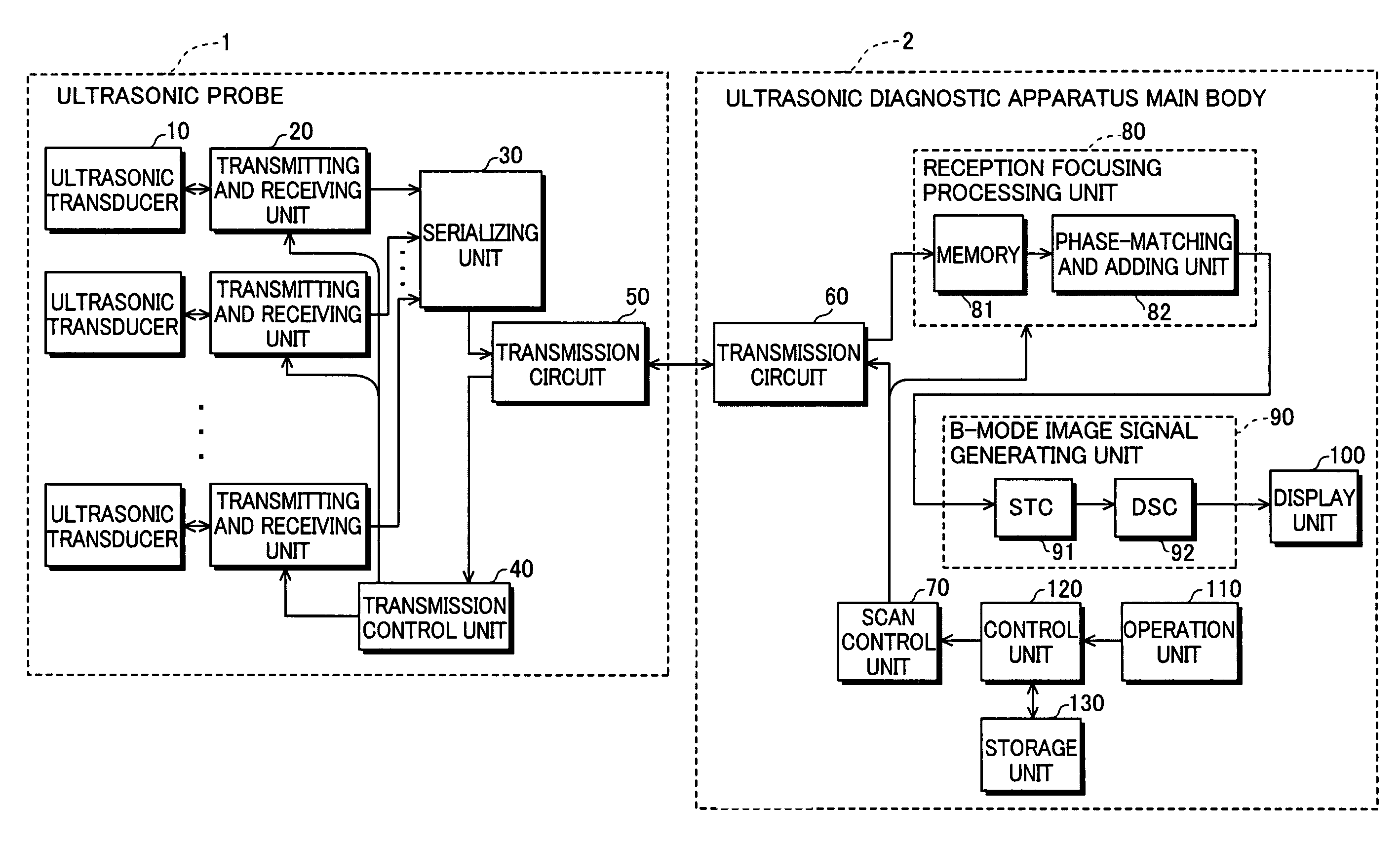
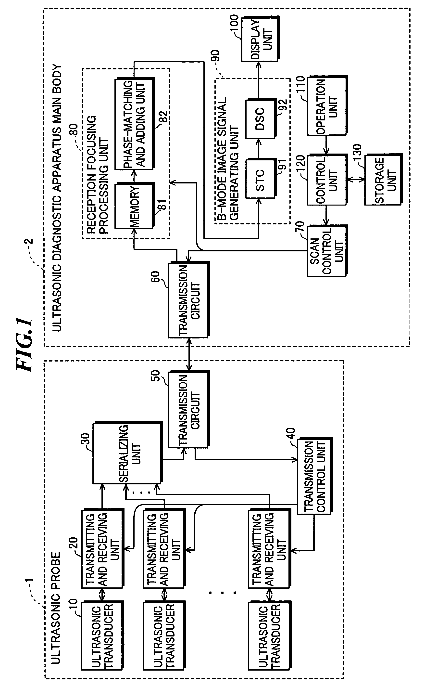
[0065]FIG. 7 is a block diagram showing a configuration of an ultrasonic probe according to a first modified example of the present invention. In the ultrasonic probe 1′ as shown in FIG. 7, a switching circuit 11 for switching the connection between the plural ultrasonic transducers 10 provided in the ultrasonic probe and the transmitting and receiving units 20 is added to the ultrasonic probe 1 as shown in FIG. 1.

[0066]Generally, in the ultrasonic probe of a linear-scan type or a convex-scan type, the object is scanned while transmission aperture and reception aperture are sequentially changed. Given that the number of ultrasonic transducers provided in the ultrasonic probe 1′ is “N” and the number of ultrasonic transducers to be used at the same time is “M” (M11 selects M ultrasonic transducers from among the N ultrasonic transducers and connects the selected M ultrasonic transducers to the M transmitting and receiving units 20, respectively. Thereby, the number of transmitting an...

second embodiment

[0115]In the second embodiment, as is the case shown in FIG. 7, a switching circuit for switching the connection between the plural ultrasonic transducers and the transmitting and receiving units provided in the ultrasonic probe may be added. Alternatively, as shown in FIG. 8, an addition circuit for adding reception signals outputted from two ultrasonic transducers at reception of ultrasonic waves may be added.


PUM


Abstract

The number of signal lines connecting an ultrasonic probe and an ultrasonic diagnostic apparatus main body is reduced or wireless communication is realized by reducing a volume of data of reception signals outputted from plural ultrasonic transducers. The ultrasonic probe includes: plural ultrasonic transducers for transmitting ultrasonic waves according to drive signals and receiving ultrasonic echoes to output reception signals; signal processing units for performing orthogonal detection processing or orthogonal sampling processing on the reception signals to generate two signals representing a complex baseband signal; sampling units for sampling the two signals to generate parallel sample data; a serializing unit for converting the parallel sample data into serial sample data; and a transmitting unit for transmitting the serial sample data.

Description

CROSS-REFERENCE TO RELATED APPLICATION[0001]The present application claims priority from Japanese Patent Applications No. 2008-290894 filed on Nov. 13, 2008 and No. 2009-061086 filed on Mar. 13, 2009, the contents of which are incorporated herein by reference in their entirety.BACKGROUND OF THE INVENTION[0002]1. Field of the Invention[0003]The present invention relates to an ultrasonic probe including plural ultrasonic transducers for transmitting and receiving ultrasonic waves, and an ultrasonic diagnostic apparatus for generating ultrasonic diagnostic images by using the ultrasonic probe.[0004]2. Description of a Related Art[0005]In medical fields, various imaging technologies have been developed for observation and diagnoses within an object to be inspected. Especially, ultrasonic imaging for acquiring interior information of the object by transmitting and receiving ultrasonic waves enables image observation in real time and provides no exposure to radiation unlike other medical ...

Claims


Application Information

Patent Timeline
Patent Type & Authority Patents(United States)
IPC IPC(8): G10K11/34A61B8/00G01S7/52G01S7/00
CPCG10K11/346A61B8/00A61B8/565G01S7/52028G01S7/5208G01S7/003A61B8/4472
Inventor KONDO, YUJI
Owner FUJIFILM CORP
Why Eureka
Try Eureka