Laterally coupled bulk acoustic wave filter with improved passband characteristics

a bulk acoustic wave and filter technology, applied in the direction of electrical equipment, impedence networks, etc., can solve the problems of large number of layers and their sensitivity to the thickness of piezolayers, not extensively studied, and fabrication process difficulty and consequently expensive, etc., to improve the quality of passband and near-passband response

Active Publication Date: 2015-12-22
TEKNOLOGIAN TUTKIMUSKESKUS VTT
View PDF14 Cites 90 Cited by
  • Summary
  • Abstract
  • Description
  • Claims
  • Application Information

AI Technical Summary

Benefits of technology

[0016]The aim of this invention is to provide a solution for improving the quality of the passband and near-passband response of an LBAW filter.
[0017]The invention is based on the observation that despite the closeness of the unwanted spurious passband close to the desired passband, the unwanted portion can be suppressed by providing a reflector stack underneath the piezoelectric filter, the reflector stack being designed so that at the frequency of the unwanted passband, shear waves pass through the reflector, whereas in the filter passband, both shear and longitudinal waves are reflected to ensure low losses.
[0023]an acoustic reflector structure in acoustic connection with the vibration layer, the reflector structure being adapted to acoustically isolate the vibration layer from its surroundings at the first frequency band more efficiently than at the second frequency band.
[0043]According to another embodiment, the desired frequency-dependent reflector effect is achieved by selecting the acoustic materials of the various layers of the reflector structure from a group of more than two materials instead of or in addition to adjusting the layer thicknesses.
[0046]The invention provides considerable advantages, the most important of which is that it makes LBAW filter more suitable for commercial RF applications due to improved passband characteristics. It has been demonstrated that in spite of the closeness of the spurious and filter passbands, by re-designing the reflector such that at the shear-wave passband frequencies, spurious shear waves pass through the reflector, while at filter passband, both longitudinal and shear waves are reflected, the unwanted passband was suppressed by 8 dB. At the same time, losses at filter passband were not significantly increased, which is a basic requirement for efficient operation of the filter. This implies a great improvement in passband quality. By further optimization, suppression of more than 10 dB can be expected.
[0047]Compared with vertically coupled BAW filters, the present structure allows for significant reduction of the number of layers needed. In particular, only one piezoactive main vibration layer and less electrode layers are needed. Consequently, the invention also relieves the manufacturing tolerance of the thickness of the piezoactive main vibration layer (as no coupling between a plurality of such layers is needed).

Problems solved by technology

The disadvantage of the vertically coupled CRFs is the need for a large number of layers and their sensitivity to the thickness of the piezolayers.
This makes the fabrication process difficult and consequently expensive.
Lateral acoustic coupling in bulk acoustic waves thin-film devices (LBAW) is a promising technology for filter fabrication, which however has not been extensively studied.
A problem with the current responses is the spurious passband below the desired passband, arising from the thickness-shear TS2 mode.
As a consequence, the thickness shear wave mode is efficiently excited and also couples electrically to the filter structure, producing an unwanted passband.
In these cases, the unwanted passbands are, however, relatively far away from the actual passband and not close to the filter passband as in the case of LBAW devices.
Therefore, the techniques and structures used with BAW CRF cannot be used to suppress the unwanted passband arising in LBAW filters.

Method used


Image

  • Laterally coupled bulk acoustic wave filter with improved passband characteristics
  • Laterally coupled bulk acoustic wave filter with improved passband characteristics
  • Laterally coupled bulk acoustic wave filter with improved passband characteristics

Examples


Embodiment Construction

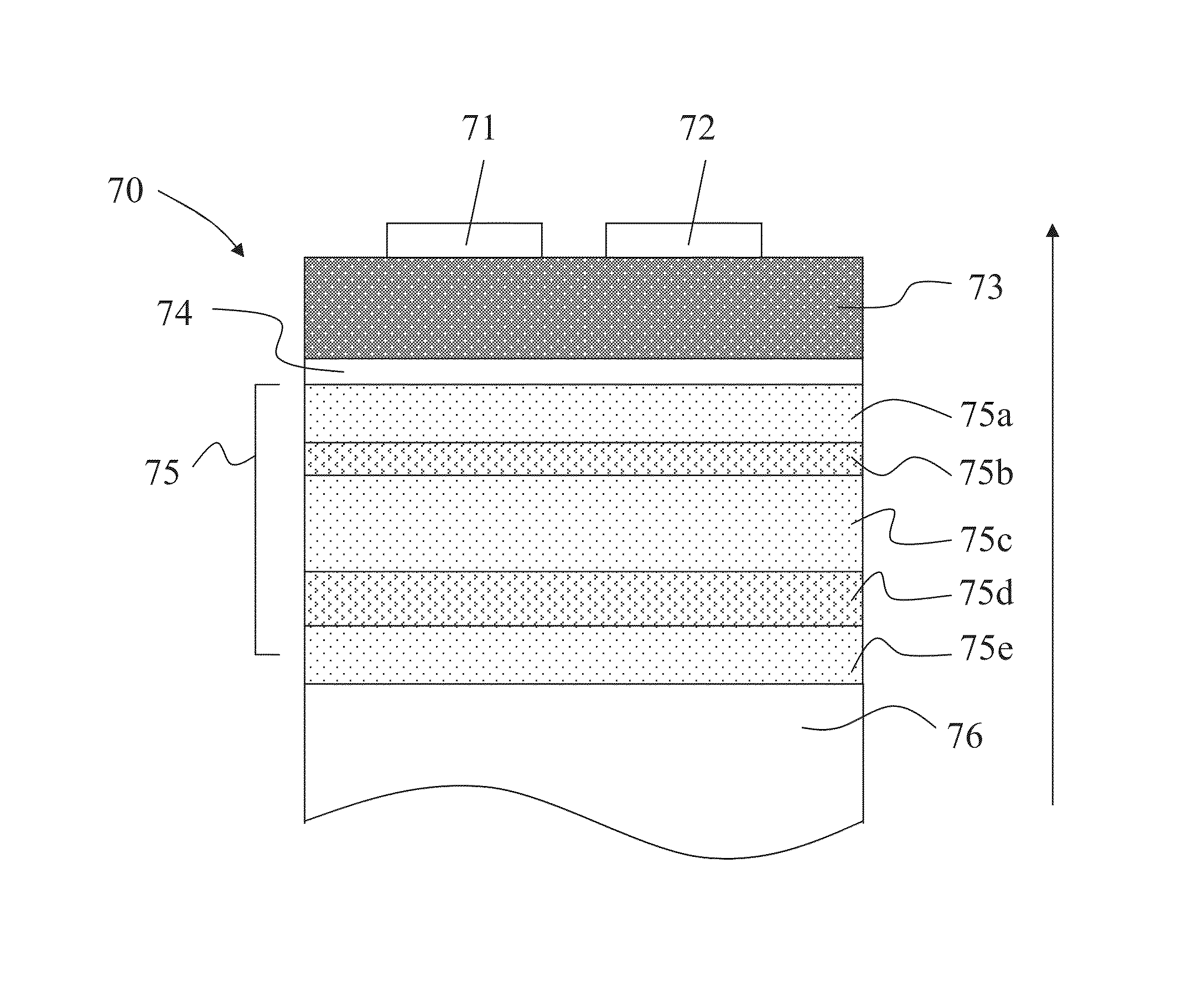
[0067]FIG. 7a shows a filter structure according to one embodiment of the invention. The structure comprises a planar piezoactive layer 73 on a planar bottom (ground) electrode layer 74. The input and output ports or electrodes 71 and 72 are made of a patterned layer on top of the piezoactive layer 73. Below the bottom electrode 74, there is an acoustic reflector 75, which is formed of several sublayers 75a-e. The sublayers comprise low-impedance layers 75a, 75c and 75e and high-impedance layers 75b and 75d in alternating manner. Below the acoustic reflector 75 is a substrate 76 supporting the whole structure and absorbing the acoustic energy passing though the acoustic reflector 75.

[0068]In more detail, the structure according to FIG. 7 comprises, listed from top to bottom, a conductive top electrode layer patterned so as to form at least two electrodes 71 and 72,[0069]a piezoactive layer 73,[0070]a conductive bottom electrode layer 74,[0071]a reflector stack comprising[0072]a low-...


PUM


Abstract

The invention relates to a laterally coupled bulk acoustic wave (LBAW) filter comprising a vibration layer for carrying bulk acoustic waves, electrode means comprising a first electrode coupled to the vibration layer for exciting to the vibration layer at least one longitudinal wave mode having a first frequency band and one shear wave mode having a second frequency band, and a second electrode coupled to the vibration layer for sensing the filter pass signal, the first and second electrodes being laterally arranged with respect to each other, and an acoustic reflector structure in acoustic connection with the vibration layer. According to the invention, the reflector structure is adapted to acoustically isolate the vibration layer from its surroundings at the first frequency band more efficiently than at the second frequency band for suppressing the effect of the shear wave mode at the second frequency band from the filter pass signal. The invention helps to improve the quality of LBAW filter passbands.

Description

FIELD OF THE INVENTION[0001]The invention relates to bulk acoustic wave (BAW) thin-film technology. In particular, the invention relates to a laterally coupled BAW (LBAW) filter and a method of filtering an RF signal with the aid of an LBAW filter. Such filters have the features of the preamble of claim 1.BACKGROUND OF THE INVENTIONBAW Resonators[0002]Bulk acoustic wave thin-film devices can be used as resonators. A schematic picture of a solidly-mounted piezoelectric BAW resonator based on thin-film technology is shown in FIG. 1. The piezoelectric thin-film layer and electrode layers that constitute the resonator transform the electric signal into acoustic vibration and vice versa. The resonator is solidly-mounted on the silicon substrate, meaning that the resonator is acoustically isolated from the substrate with an acoustic reflector consisting of alternating layers of high and low acoustic impedance (Z) materials (acoustic Bragg reflector, or “acoustic mirror”). This type of res...

Claims


Application Information

Patent Timeline
Patent Type & Authority Patents(United States)
IPC IPC(8): H03H9/15H03H9/54H03H9/56
CPCH03H9/564H03H9/54H03H9/02086H03H9/02228H03H9/175H03H3/04H03H9/0211
Inventor MELTAUS, JOHANNAPENSALA, TUOMAS
Owner TEKNOLOGIAN TUTKIMUSKESKUS VTT
Why Eureka
Try Eureka