Sensing apparatus for detecting and determining the width of media along a feed path

a technology of sensing apparatus and feed path, which is applied in the direction of thin material processing, article separation, printing, etc., can solve the problems of inability to provide the printer with an ability, the conventional approach yields undesirable, and the conventional approach fails to provide automatic adjustment of printhead pressure, so as to reduce manufacturing costs and assembly complexity, overcome deficiencies and shortcomings

Inactive Publication Date: 2015-12-22
HAND HELD PRODS
View PDF134 Cites 140 Cited by
  • Summary
  • Abstract
  • Description
  • Claims
  • Application Information

AI Technical Summary

Benefits of technology

[0006]The present invention is designed to overcome the deficiencies and shortcomings of the devices conventionally known and described above. The present invention is designed to reduce the manufacturing costs and the complexity of assembly. In all exemplary embodiments, the present invention is directed to sensing apparatus or sensors and methods of use to determine a width of a media sheet or web moving along a defined media path within a printing system. In an exemplary embodiment, a carriage or base is provided which is mountable within a printing system. A pair of adjustable media guides is provided and connected to the carriage via channels or slots which are located within a portion of the carriage. The media guides are configured to receive and maintain media or a web for printing and preferably axially spaced apart along the length of the carriage. Further, the media guides are configured and adapted such that they can be manipulated or moved along a horizontal axis of the carriage in a sliding manner. In exemplary embodiments, the sliding movement of the guides along the horizontal axis occurs in a synchronized manner. In still other exemplary embodiments, the guides are configured such that the center line of media which is passing along a media feed path is maintained along the centerline of the print station.
[0007]In all exemplary embodiments, a sensor is provided, affixed to the carriage and in signal communication with control circuitry of the printing system. The sensor is configured and operable for emitting at least one optical signal or light beam through at least one aperture located in the carriage. At least one of the media guides are provided with a tab or other obstruction which is configured and operable for protruding into at least a portion of the path of the at least one optical signal or light beam emitted from the sensor at defined locations, the defined locations corresponding to the widths of various media types used within the printing system. As the media guides move about the horizontal axis of the carriage, the tab may block or otherwise interrupt or obstruct the at least one optical signal or light beam, thereby reflecting the at least one optical signal or light beam back to the sensor and thuds signaling the sensor and the printer of the media's detection and width. By detecting and determining the media width in the printing station, automatic adjustments can be made to the printhead pressure, ribbon supply tension, ribbon supply take up, and rewind tension, thereby ensuring a higher quality printed image and prolonged printer operation. Further, by detecting and determining the media width in the printer station, associated software can compare the width of the image to be printed to the media width and notify the operator that they may be printing off the media.

Problems solved by technology

Heretofore, conventional approaches yield undesirable results.
For instance, conventional approaches fail to provide for automatic adjustments in printhead pressure, ribbon supply and take up tension and rewinder tension due to variances in the media width.
Further, conventional approaches fail to provide the printer with an ability to compare the width of the image to be printed with the actual media width.
Such failures oftentimes lead to off center image printing, printing defects or printer failure.
Indeed, should the media width not be accommodated for, wax (ink) may be undesirably deposited on the platen roller or firing elements on the printhead in free space may occur.
One skilled in the art will appreciate that firing elements in free space may cause the elements to overheat and burn out.

Method used


Image

  • Sensing apparatus for detecting and determining the width of media along a feed path
  • Sensing apparatus for detecting and determining the width of media along a feed path
  • Sensing apparatus for detecting and determining the width of media along a feed path

Examples


Embodiment Construction

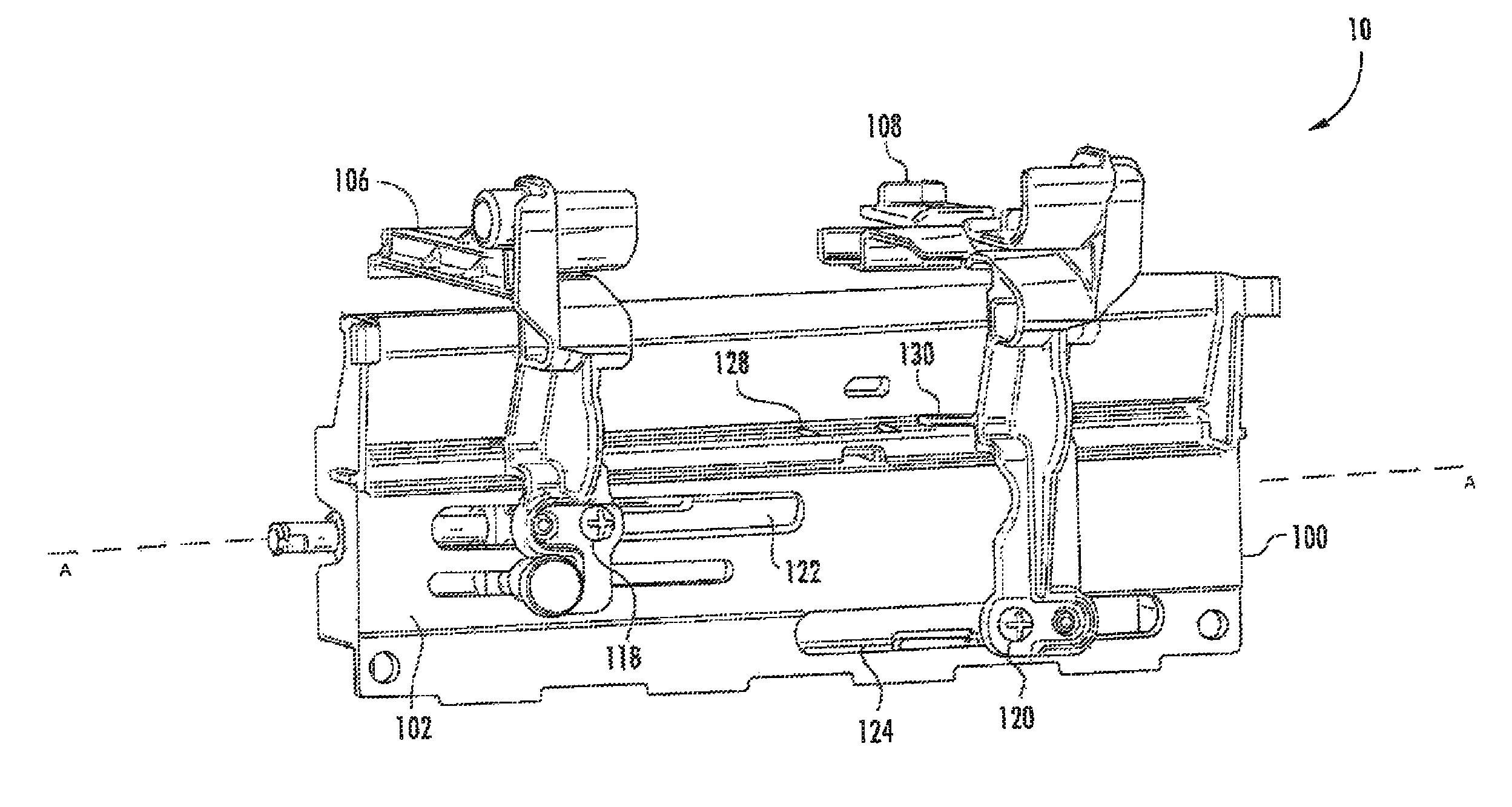
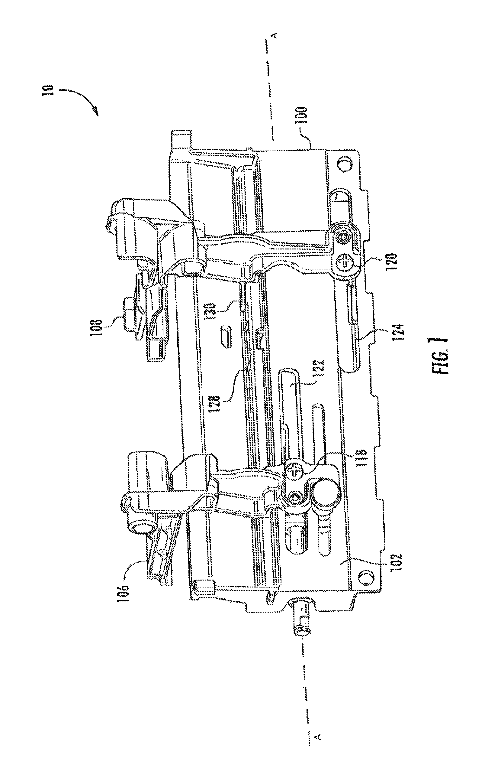
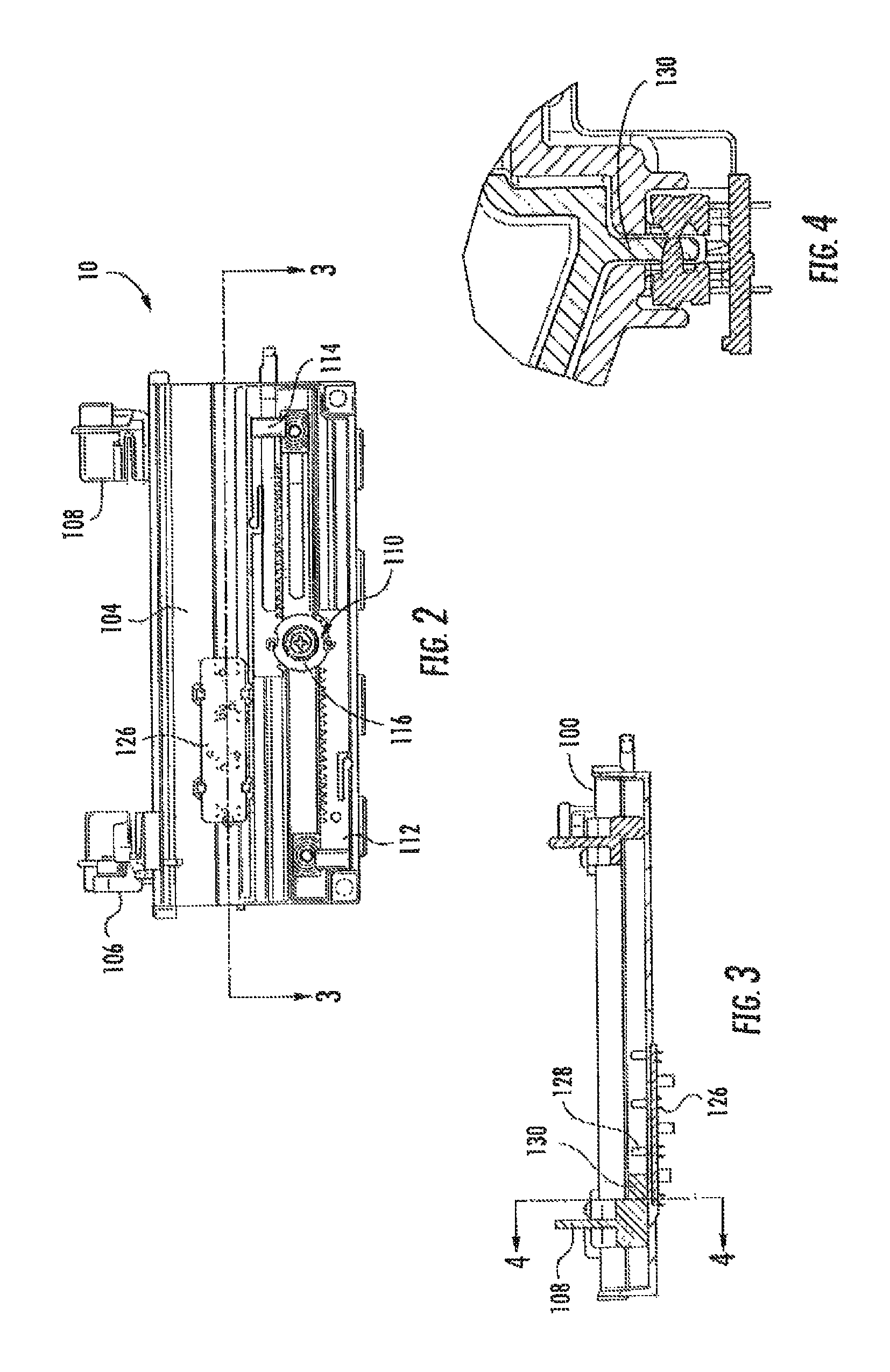
[0018]The present invention will now be described more fully hereinafter with reference to the accompanying drawings in which exemplary embodiments of the invention are shown. However, this invention may be embodied in many different forms and should not be construed as limited to the embodiments set forth herein. These exemplary embodiments are provided so that this disclosure will be both thorough and complete, and will fully convey the scope of the invention to those skilled in the art. Further, as used in the description herein and throughout the claims that follow, the meaning of “a”, “an”, and “the” includes plural reference unless the context clearly dictates otherwise. Also, as used in the description herein and throughout the claims that follow, the meaning of “in” includes “in” and “on” unless the context clearly dictates otherwise.

[0019]Methods, apparatus and systems are presented herein for feeding original image media web and / or printable media into a printing system an...


PUM


Abstract

A system to determine the presence and width of a media within a printing system is disclosed which includes a pair of adjustable media guides is provided about a carriage and is axially spaced apart along the length of the carriage. The guides may be manipulated along a horizontal axis in a sliding, synchronized manner and such that the center line of media is maintained along the centerline of the print station. A sensor is provided and affixed to the carriage, the sensor being operable for emitting an optical signal through an aperture located in the carriage. At least one of the guides includes an obstruction which may protrude into the path of the optical signal at defined locations. As the guides move about the horizontal axis, the obstruction may block or otherwise interrupt the optical signal, thereby signaling the sensor and the printer of the media's presence and width.

Description

CROSS-REFERENCE TO RELATED APPLICATION(S)[0001]This application claims priority to provisional patent application 61 / 488,890, filed May 23, 2011, and entitled “Media Width Sensor”, the contents of which are incorporated in full by reference herein.FIELD OF INVENTION[0002]The present invention generally relates to the field of image forming apparatus and devices, and in particular, to sensors operable for determining the width of a media sheet or web as it moves along a media path within a print station of the image forming apparatus or device.BACKGROUND[0003]Printing systems such as copiers, printers, facsimile devices or other systems having a print engine for creating visual images, graphics, texts, etc. on a page or other printable medium typically include various media feeding systems for introducing original image media or printable media into the system. Examples include thermal transfer printers. Typically, a thermal transfer printer is a printer which prints on media by melt...

Claims


Application Information

Patent Timeline
Patent Type & Authority Patents(United States)
IPC IPC(8): B65H9/04B65H1/00H04N1/00
CPCH04N1/00689B65H9/04H04N1/0071H04N1/00732H04N1/00734H04N1/00755H04N1/00771H04N1/00779B65H2801/06B65H2553/414B65H2511/22B65H2511/12B65H2404/742B65H2403/411B65H2220/03B65H2220/02B65H2220/04B65H2220/11
Inventor BOUVERIE, WILLIAM M.HITZ, MARK ALLENTOBIN, DWAYNE STEVENHATLE, RICHARD
Owner HAND HELD PRODS
Why Eureka
Try Eureka