Knee prosthesis

a knee joint and prosthesis technology, applied in the field of knee joints, can solve the problems of no longer providing support to the knee joint, ligament damage or rupture, etc., and achieve the effect of preventing the paradoxical roll forward

Active Publication Date: 2015-12-29
AESCULAP IMPLANT SYST
View PDF64 Cites 1 Cited by
  • Summary
  • Abstract
  • Description
  • Claims
  • Application Information

AI Technical Summary

Benefits of technology

[0005]The present invention identifies and overcomes a further shortcoming of the prior art. As stated above, true anatomical movement would allow rollback and translation of the femoral condyles on the tibia, all while also allowing rotational movement during flexion / extension. It has now been identified that knee prosthesis designs, which utilize bearing surfaces to allow flexion / extension and enable rotational movement, often exhibit a forward translation of the femoral component upon the tibial component. This phenomenon, called “paradoxical roll forward”, prevents the knee prosthesis from accurately replicating the anatomic movement of a natural knee. Embodiments of the present invention prevent paradoxical roll forward and enable true anatomical movement of the knee.
[0007]A natural knee contains a posterior cruciate ligament which helps provide stability and strength to the knee joint. This ligament may become damaged or ruptured and, thus, no longer provide support to the knee joint. The present invention provides prostheses which employ cruciate-substituting or cruciate-retaining knee prosthesis architectures for achieving kinematic knee motion. Embodiments of the present invention contain components which function to substitute for damaged or ruptured posterior cruciate ligament. Other embodiments of the present invention work to supplement the cruciate ligament when it is healthy enough to be retained in the knee prosthesis.
[0009]In another embodiment, the knee prosthesis includes a femoral component with two condyles, with an opening disposed between the two condyles, and a tibial component having bearing surfaces to support each of the femoral component condyles. The medial and lateral femoral condyles are asymmetrical in an anterior-posterior cross-section. The lateral condyle has a similar architecture of the lateral condyle of the first embodiment, but the medial condyle of this embodiment has at least one region of uniform radius. Similarly, the medial and tibial bearing surfaces are asymmetrical in an anterior-posterior cross-section. The femoral component and tibial component are engageable by contact between the femoral condyles and tibial bearing surfaces. However, the lateral and medial bearing surfaces remain symmetrical in the lateral-medial cross-section. During flexion of the femoral and tibial components from about 0° to about 90°, a period of flexion in which other knee designs are prone to paradoxical roll forward, an anterior lip of the medial tibial bearing surface functions to prevent roll forward of the femoral component of the present knee prosthesis. The anterior-posterior design architecture of the medial tibial bearing surface constrains the translation of the femoral component and works with the uniform radius of curvature of the medial femoral condyle to also prevent the paradoxical roll forward. The asymmetrical lateral and medial femoral condyles, and the asymmetric lateral and medial tibial bearing surfaces enable the condyles to translate posteriorly at different rates and cause rotation between the tibial and femoral components. Thus, by moving the femoral and tibial components in flexion from about 0° to about 165°, the contact regions between the femoral component and the tibial component prevent roll forward, enable roll back, and cause rotation between the tibial and femoral components.

Problems solved by technology

This ligament may become damaged or ruptured and, thus, no longer provide support to the knee joint.

Method used


Image

  • Knee prosthesis
  • Knee prosthesis
  • Knee prosthesis

Examples


Embodiment Construction

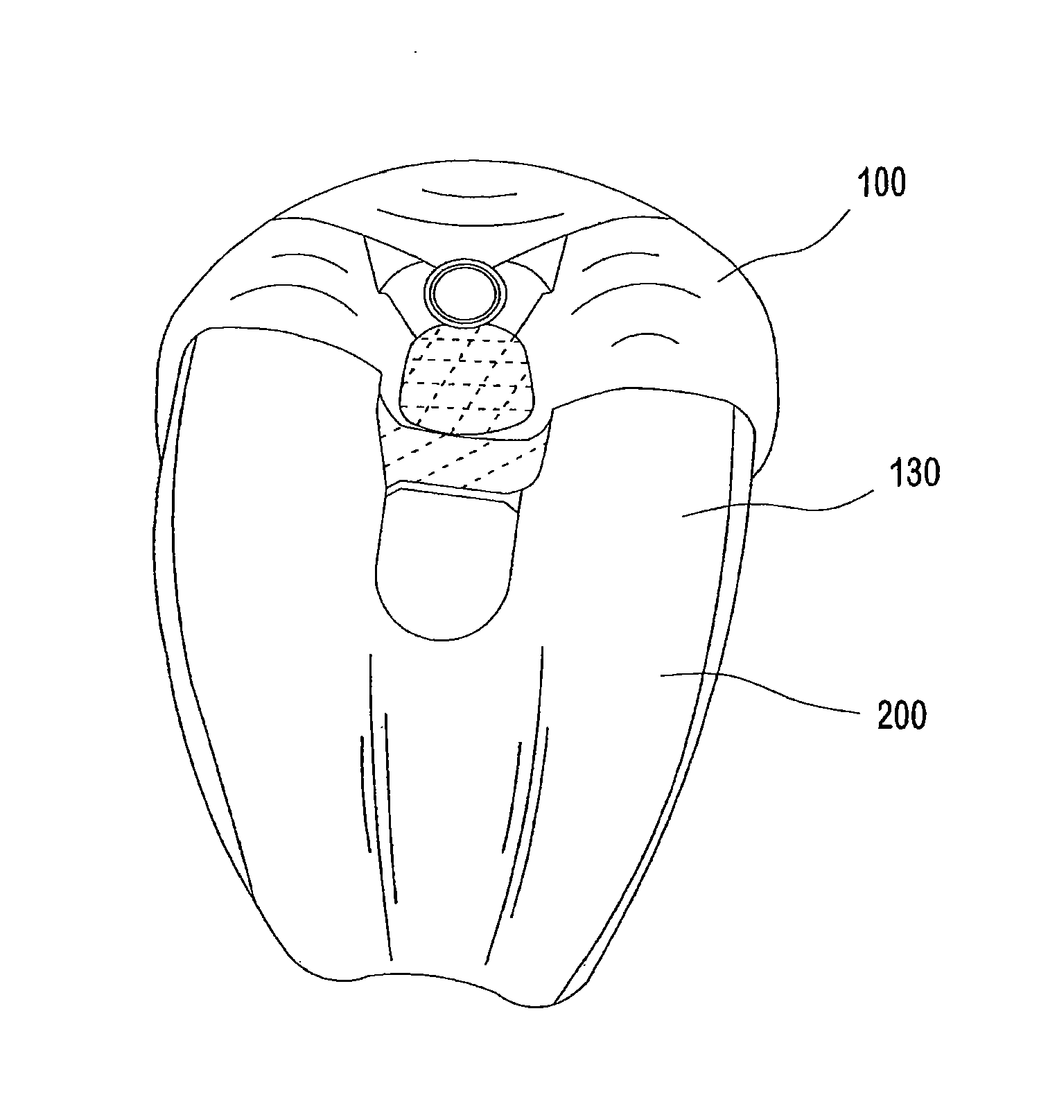
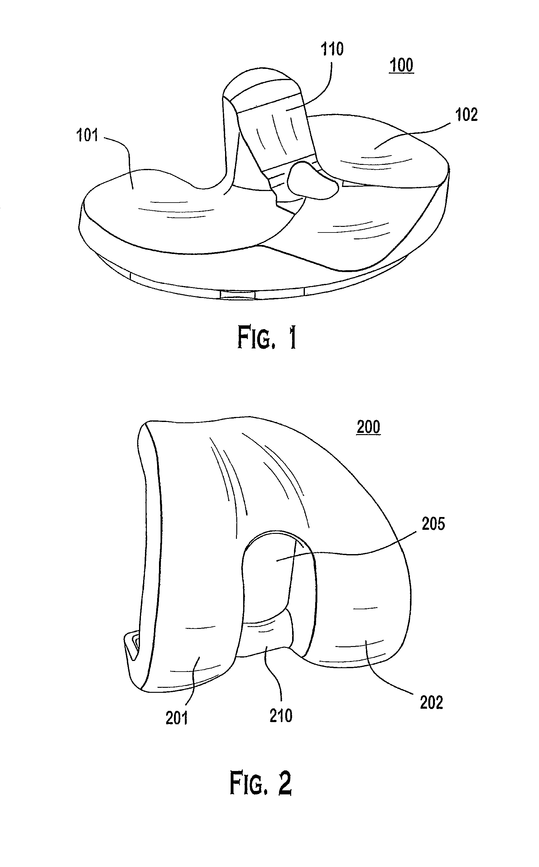
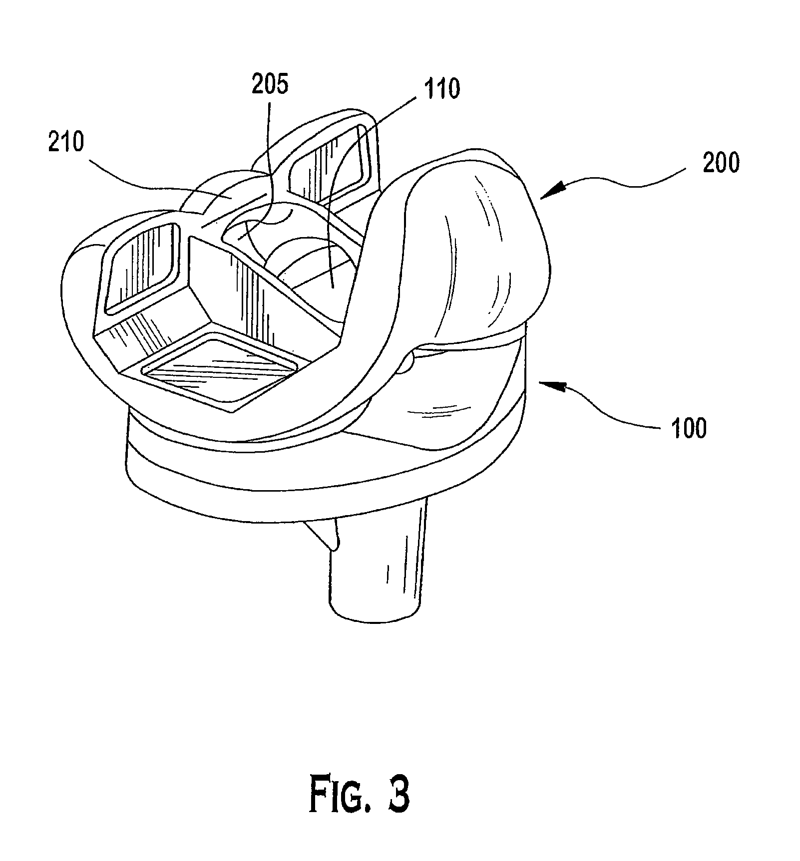
[0037]The present invention provides a knee prosthesis which allows for anatomically correct knee movement. It does so by providing an upper, or femoral, component which is designed to mechanically interact with a lower, or tibial, component to achieve kinematic movement consistent with a natural knee joint. Generally, the two pieces interact by providing several different contact surfaces, not all of which are engaged between the two components of the knee throughout the range of motion.

[0038]Two such contact surfaces are the load bearing condylar surfaces between the femoral component and the tibial component. These surfaces are defined by medial and lateral condylar surfaces which are referred to as the load bearing surfaces for a given knee joint. Specifically, a medial load bearing surface is defined between the medial femoral condyle and its counterpart on the tibial component, namely a medial tibial accommodating surface. Likewise, a lateral load bearing surface is defined be...


PUM


Abstract

A knee prosthesis having a femoral component with two condyles, an opening disposed between the two condyles, and a tibial component having bearing surfaces to engage and support each of the femoral component condyles. Moving the femoral and tibial components in flexion from about 0° to about 165° causes medial pivot rotation of the femoral component upon the tibial component. Rotation may be caused by interaction between an asymmetrical cam extending between the femoral condyles and a post disposed between the bearing surfaces and extending superior from the tibial component. Rotation may alternatively be caused by asymmetrical medial and lateral condyles which translate posteriorly upon respective medial and lateral bearing surfaces at disparate rates, without a femoral cam, a tibial post, or a post / cam contact surface. Embodiments of the knee prosthesis may be used in cruciate-substituting or cruciate-retaining procedures. Embodiments of the knee prosthesis may also prevent roll forward.

Description

[0001]This application is the U.S. National Phase application of PCT International Application No. PCT / US2009 / 069163, filed Dec. 22, 2009, which is a continuation-in-part of U.S. Non-provisional application Ser. No. 12 / 484,594, filed Jun. 15, 2009, which claims the benefit of priority of U.S. Provisional Application Ser. No. 61 / 140,183, filed Dec. 23, 2008, all of which are hereby fully incorporated by reference as if fully set forth herein.FIELD OF INVENTION[0002]The field of invention relates to artificial joints, and more particularly to knee prostheses.BACKGROUND[0003]As is the case with many joint prostheses or replacements, replicating natural anatomical movement through artificial mechanical devices proves challenging. This is true especially with the knee, which allows for relative complex movement and kinematics between the femoral condyles and the tibia. This relative motion is complex in that it accounts for both rolling and sliding between the contact surfaces at varying...

Claims


Application Information

Patent Timeline
Patent Type & Authority Patents(United States)
IPC IPC(8): A61F2/38A61F2/30
CPCA61F2/38A61F2/3886A61F2230/0006A61F2002/30688A61F2002/30116
Inventor MIHALKO, WILLIAMSALEH, KHALED J.MOUSSA, SAIDMOUILLET, DOMINIQUE
Owner AESCULAP IMPLANT SYST
Why Eureka
Try Eureka