Receiving apparatus for differential signals
a technology of differential signals and receiving apparatuses, which is applied in the direction of digital transmission, line-faulst/interference reduction, baseband system details, etc., can solve the problems of displaced discrimination timing and deterioration of signal quality
- Summary
- Abstract
- Description
- Claims
- Application Information
AI Technical Summary
Benefits of technology
Problems solved by technology
Method used
Image

Examples
first exemplary embodiment
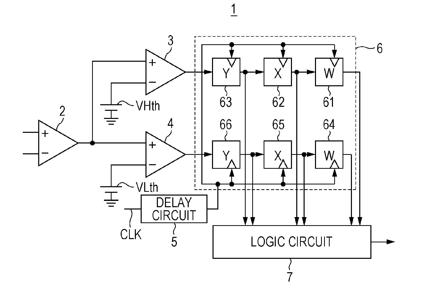
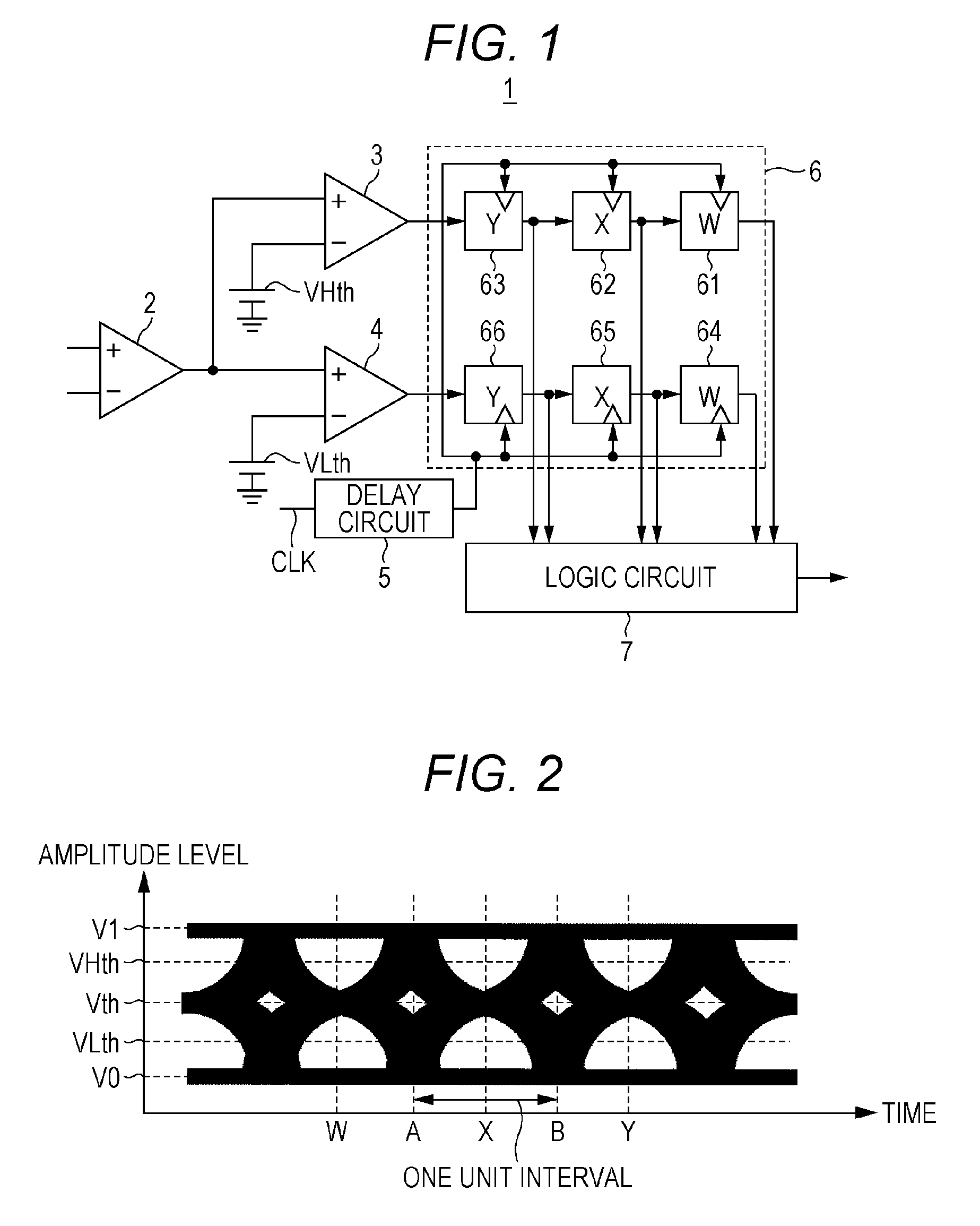
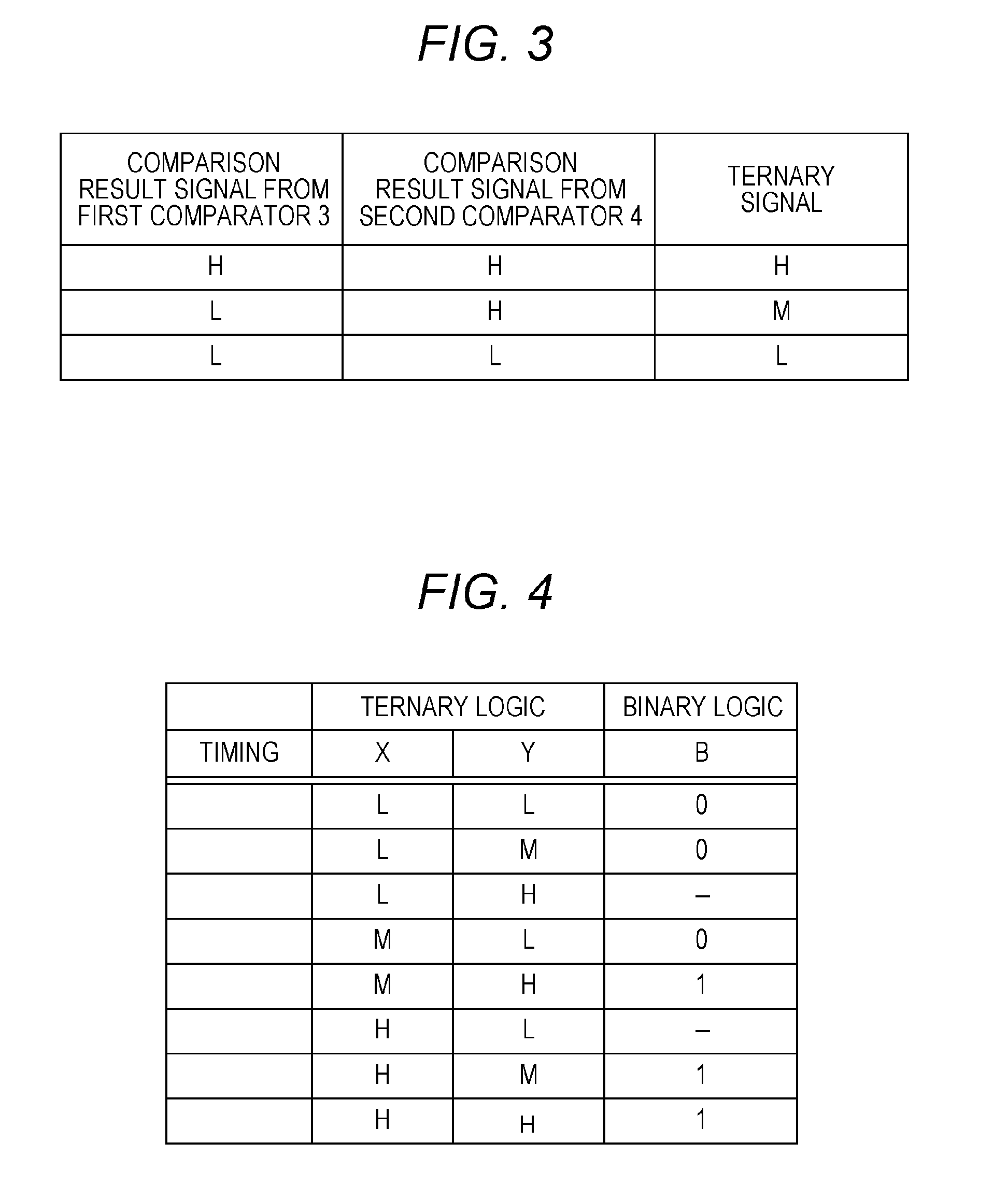
[0042]In a conventional receiving apparatus, an amplitude level of differential signals is binary discriminated, at a binary discrimination timing B (see FIG. 2), with a voltage level between a voltage level V0 corresponding to logical value 0 and a voltage level V1 corresponding to logical value 1 as a reference level Vth, and a binary signal is output as a result corresponding to the binary discrimination. On the other hand, in receiving apparatus 1 according to the first exemplary embodiment, the amplitude level of differential signals is ternary discriminated at ternary discrimination timings X and Y (see FIG. 2) before and after the binary discrimination timing B, and a ternary signal corresponding to the ternary discrimination is generated. After that, the amplitude level of the differential signals is ternary discriminated based on the ternary signal. When the ternary discrimination of the amplitude level of differential signals is performed, a first threshold level VHth and ...
second exemplary embodiment
[0073]In receiving apparatus 1 according to the above-described first exemplary embodiment, ternary discrimination is performed to determine a binary value indicating logical value 0 or logical value 1 for differential signals having a large skew. However, receiving apparatus 1A according to a second exemplary embodiment is configured to select ternary discrimination and conventional binary discrimination. With this configuration, ternary discrimination can be performed when differential signals having a large skew are input; and binary discrimination can be performed when differential signals having almost no skew are input.
1. Configuration
[0074]FIG. 7 is a block diagram showing structural elements of receiving apparatus 1A according to the second exemplary embodiment of the present disclosure. Compared to receiving apparatus 1 of FIG. 1, receiving apparatus 1A of FIG. 7 is equipped with logic circuit 7A instead of logic circuit 7 and is further equipped with third comparator 8 hav...
third exemplary embodiment
[0090]In the above-described receiving apparatus 1A according to the second exemplary embodiment, selection is made, by receiving the training signal TS, between outputting the binary signal determined from the ternary signals at the ternary discrimination timings W, X, and Y and outputting the binary signal latched by shift register circuit 9; however, the present disclosure is not limited to this manner. For example, as in the present exemplary embodiment, conversion into ternary signals may be also performed at the binary discrimination timings A and B; and based on the converted ternary signals, selection may be made between outputting the binary signal determined based on the ternary signals at the ternary discrimination timings W, X, and Y and outputting the binary signal latched by shift register circuit 9.
1. Configuration
[0091]FIG. 9 is a block diagram showing structural elements of receiving apparatus 1B according to a third exemplary embodiment of the present disclosure. C...
PUM
 Abstract
Description
Claims
Application Information
 - R&D
- Intellectual Property
- Life Sciences
- Materials
- Tech Scout
- Unparalleled Data Quality
- Higher Quality Content
- 60% Fewer Hallucinations
Browse by: Latest US Patents, China's latest patents, Technical Efficacy Thesaurus, Application Domain, Technology Topic, Popular Technical Reports.
© 2025 PatSnap. All rights reserved.Legal|Privacy policy|Modern Slavery Act Transparency Statement|Sitemap|About US| Contact US: help@patsnap.com