Clock grid driven by virtual leaf drivers

a virtual leaf driver and clock grid technology, applied in the field of integrated circuits, can solve the problem of limiting the operating frequency of the ic, and achieve the effects of ensuring synchronization, normalizing the amount of clock signal skew experienced, and reducing the maximum skew between points on the clock grid in the region surrounding the virtual leaf driver nodes

Active Publication Date: 2009-01-06
ADVANCED MICRO DEVICES INC
View PDF23 Cites 19 Cited by
  • Summary
  • Abstract
  • Description
  • Claims
  • Application Information

AI Technical Summary

Benefits of technology

[0010]The use of virtual leaf driver nodes to drive a clock grid of an integrated circuit may, in some embodiments, reduce and help normalize the amount of clock signal skew experienced at different locations on the clock grid. An integrated circuit may include a large number of clocked elements such as registers, flip-flops, etc. whose operation is synchronized by one or more clocks. For example, an operation performed by circuitry on one side of the die may need to occur at precisely the same time as another operation performed by circuitry on the other side of a die for an IC. In order to assure synchronization of these events, a clock grid driven by virtual leaf driver nodes may be provided in the IC. The clock tree driving the clock grid may include a tier of leaf buffers. The output of a leaf buffer may be split or ramified, and the branches of the output connected to separate points on the clock grid, according to some embodiments. The output of a leaf buffer may be split into virtually any number of signal paths each connecting the leaf buffer to one or more points distributed across the clock grid.
[0011]In one embodiment, the feeder paths along which the clock signal branches are routed from the output of the leaf buffer to their connection points on the clock grid may be the same length. In another embodiment, the feeder paths may be of different lengths, but the propagation delay experienced by the clock signal branch may be the same for all feeder paths connected to the output of a particular leaf buffer. The terminal end of each feeder path may be connected to a point on the clock grid, which serves as a virtual leaf driver node. By insuring that the propagation delay for each feeder element is the same, the skew of the clock signal from one virtual leaf driver node to another may be eliminated. Note that clock signal skew may still exist between the output of the leaf buffer and the outputs of the corresponding virtual leaf driver nodes, however when measured relative to one another the outputs of the virtual leaf driver nodes may be in phase. Therefore, the maximum skew between points on the clock grid in a region surrounding the virtual leaf driver nodes may be significantly decreased as compared to that of a system in which the corresponding leaf buffer is connected to the grid at a single point.
[0012]In some embodiments, the load attached to the portion of the clock grid driven by one leaf buffer may be greater than that attached to a different portion of the clock grid. In one embodiment, the registers of the circuitry attached to both portions of the grid may be positive-edge triggered and the tolerable clock skew attributable to waveform distortion may be constant. The leaf buffer driving the lighter load may produce an output waveform that meets the clock skew requirement using a weaker pull-up transistor than that in the buffer driving the portion of the clock grid to which the heavier load is connected. The same relationship may hold true for falling-edge triggered logic and the pull-down transistors of leaf buffers. By tailoring the relative strengths of leaf buffer output transistors based on the load being driven and the type of edge utilized by the logic in a particular portion of an IC, substantial savings in power consumption and / or real estate may be realized.

Problems solved by technology

Integrated circuit (IC) technology typically includes complex logic core designs that rely on one or more clocks for operational synchronization.
Delay along this path may cause the edge of the clock signal at the consumer to lag that of the output of the leaf and this delay may differ between two consumers at different points on the grid.
The skew thus introduced between clock signals feeding logic at various attach points may limit the operating frequency of the IC.

Method used


Image

  • Clock grid driven by virtual leaf drivers
  • Clock grid driven by virtual leaf drivers
  • Clock grid driven by virtual leaf drivers

Examples


Embodiment Construction

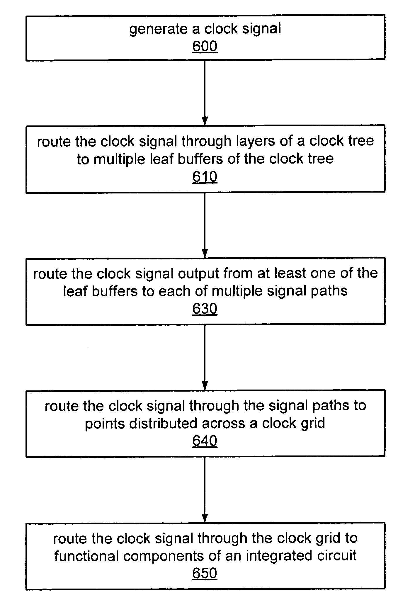
[0027]In many IC designs, the area devoted to clock tree buffers may be limited and therefore the number of groups of leaf buffers available to drive clock grid lines may also be limited. Examples of such designs may be complex microprocessors or multi-core processor chips. At the same time it may be desirable to include many clock grid lines in these designs in order to minimize the average distance from a clock consuming functional block to a clock grid connection point. It may also be desirable to operate such ICs at the maximum possible clock rate, thus minimizing the design's tolerance for clock skew. In some embodiments, the use of virtual leaf driver nodes may allow a leaf buffer to drive a number of clock grid lines with minimal skew between the different clock grid lines.

[0028]FIG. 5 illustrates a technique for routing the output of a leaf buffer to clock grid elements that may reduce clock signal skew between different points on the clock grid, according to one embodiment....


PUM


Abstract

Various embodiments of methods and systems for providing virtual leaf driver nodes in a clock tree to drive a clock grid of an integrated circuit are disclosed. An integrated circuit may include a large number of clocked elements such as registers, flip-flops, etc. whose operation is synchronized by one or more clocks. For example, an operation performed by circuitry on one side of the die may need to occur at precisely the same time as another operation performed by circuitry on the other side of the die. In order to assure synchronicity of these events, a clock grid may be provided in the IC that is driven by virtual leaf driver nodes. The clock tree driving the clock grid may include a tier of leaf buffers. The output of a leaf buffer may be split, and the branches of the output connected to separate points on the clock grid.

Description

BACKGROUND OF THE INVENTION[0001]1. Field of the Invention[0002]This invention is related to the field of integrated circuits, and more particularly, to driving a clock grid of an integrated circuit.[0003]2. Description of the Related Art[0004]Integrated circuit (IC) technology typically includes complex logic core designs that rely on one or more clocks for operational synchronization. Some of the desirable qualities for a clock signal may be an extremely small period, very short rise and / or fall times, low jitter, available everywhere on the chip with very low skew, and the ability to drive heavy loads at any point on the chip, while consuming the least possible amount of power.[0005]One common approach to the design of clock distribution circuitry is a “tree” of buffered runs in which the number of buffers from the origin of the clock signal to any particular “leaf” node is kept constant in order to minimize skew. FIG. 1 illustrates the hierarchical organization of such a convent...

Claims


Application Information

Patent Timeline
Patent Type & Authority Patents(United States)
IPC IPC(8): G06F17/50G06F9/45
CPCG06F30/396G06F30/327
Inventor JOHNSON, SCOTT C.WALTERS, DONRACHALA, RAVINDERMOENCH, JERRY
Owner ADVANCED MICRO DEVICES INC
Why Eureka
Try Eureka