Synchronization technique for high speed memory subsystem

a high-speed memory and sub-system technology, applied in the field of memory sub-systems, can solve the problems of increasing the amount of time, and affecting the reliability of data transmission

Active Publication Date: 2008-12-23
CISCO TECH INC
View PDF16 Cites 9 Cited by
  • Summary
  • Abstract
  • Description
  • Claims
  • Application Information

AI Technical Summary

Benefits of technology

[0019]Advantageously, the novel technique is capable of synchronizing data groupings having substantial skew by providing varying amounts of synchronization logic: The synchronization technique does not require additional interface signals to indicate when data is valid at the memory controller. The novel synchronization technique further enables the memory bus to be substantially wide and tolerate skewed data for many data groups that can span multiple clock cycles.

Problems solved by technology

For proper operation of the memory subsystem, clock signals should arrive at bus interface circuitry at the same time; otherwise, reliable data transmission is not ensured.
For example, if a bus interface circuit receiving data is “clocked” later than others, the earlier-clocked bus interface circuits may overwhelm the data before it is stored at its proper destination.
This lack of simultaneity in reception of the clock signals, i.e., clock skew, directly increases the amount of time that the data must remain stable on the memory bus to ensure reliable data transmission; this, in turn, increases the time required for each data transfer on the bus and, thus reduces the speed and performance of the memory subsystem.
However, there is still some degree of error in the routing because the signals carried over these traces may be routed through different layers of the PCB having different impedance characteristics that translate into timing differences.
Here, the 256 bits of data are spread over a large area of the die and the reluctance on behalf of certain ASIC vendors to manually place and tune individual bits during placement may result in such skew.
The skew in the memory subsystem may cause phase differences between the clock signals (on the order of a couple of nsecs) that results in the signals being entirely asynchronous.
Operation of the memory subsystem at such high data rates may, in turn, result in portions of the read data being spread over multiple clock boundaries.
Capturing the data within an individual grouping at a clock boundary can be difficult, but manageable.
Yet, such phase misalignment may cause portions of a 256-bit data “word” returned by the memory devices in response to a read request to arrive at the controller spread out over three different clock cycles, thus making it impossible to capture the entire data across the 256-bit bus portion 126 at the same clock boundary.

Method used


Image

  • Synchronization technique for high speed memory subsystem
  • Synchronization technique for high speed memory subsystem
  • Synchronization technique for high speed memory subsystem

Examples


Embodiment Construction

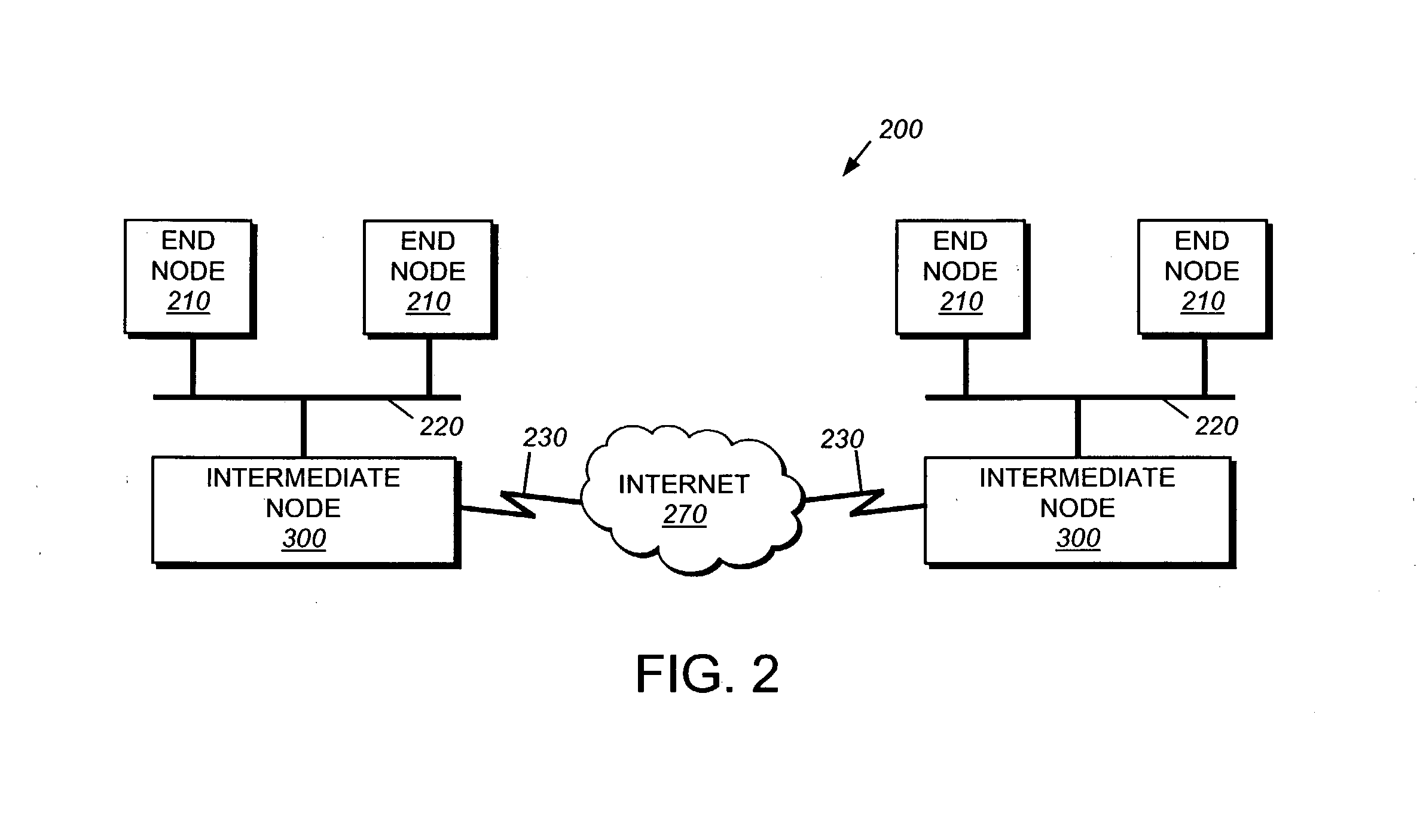
[0028]FIG. 2 is a schematic block diagram of a computer network 200 that can be advantageously used with the present invention. The computer network 200 comprises a collection of communication links and segments connected to a plurality of nodes, such as end nodes 210 and intermediate network nodes 300. The network links and segments may comprise local area networks (LANs) 220, wide area networks (WANs) such as Internet 270 and WAN links 230 interconnected by intermediate network nodes 300, such as network switches or routers, to form an internetwork of computer nodes. These inter-networked nodes communicate by exchanging data packets according to a predefined set of protocols, such as the Transmission Control Protocol / Internet Protocol (TCP / IP) and the Internetwork Packet eXchange (IPX) protocol.

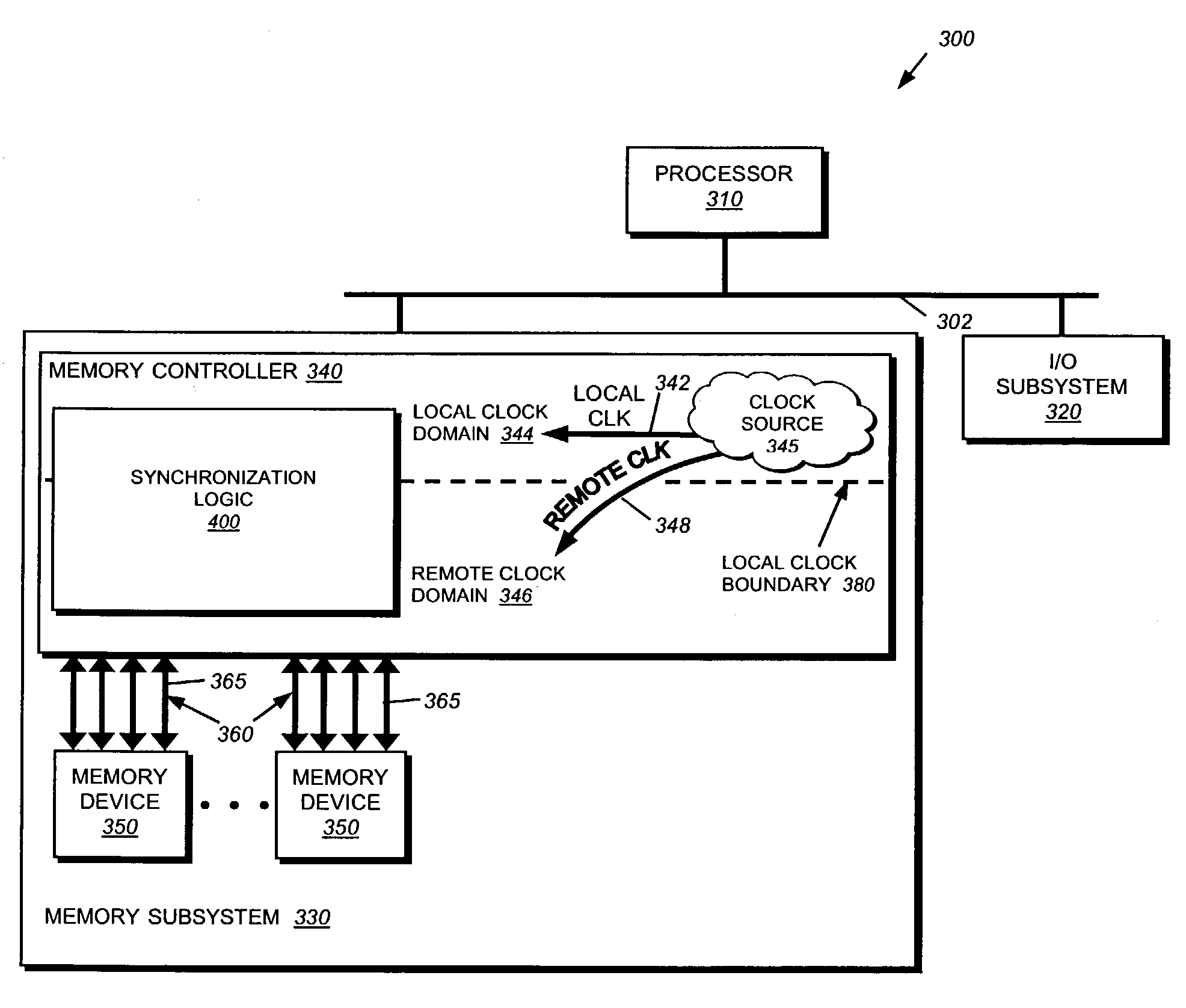
[0029]FIG. 3 is a schematic block diagram of an illustrative intermediate network node 300, such as a router or switch, having a plurality of subsystems, including a processor 310 coupled t...


PUM


Abstract

A technique synchronizes data retrieved from memory devices at a memory controller of a high-speed memory subsystem. Each memory device is organized into a plurality of data groupings. The memory controller stores (via one or more write operations) a known synchronization (sync) pattern at each data grouping on the memory devices and then retrieves (via one or more read operations) that sync pattern from the groupings. Synchronization logic located at a local clock boundary of the memory controller is configured to recognize the retrieved sync pattern and “automatically” synchronize all pieces of data retrieved from the data groupings, even though there may be substantial skew between the groupings.

Description

FIELD OF THE INVENTION[0001]The invention relates generally to memory subsystems and, more specifically, to synchronizing data retrieved from high speed memory devices of a memory subsystem within a networking device, such as an intermediate network node.BACKGROUND OF THE INVENTION[0002]A computer network is a geographically distributed collection of interconnected communication links for transporting data between nodes, such as computers. Many types of computer networks are available, with the types ranging from local area networks (LANs) to wide area networks (WANs). A plurality of LANs may be further interconnected by an intermediate network node, such as a router or switch, to form an inter-network of nodes that extends the effective “size” of the computer network by increasing the number of communicating nodes. The nodes typically communicate by exchanging discrete frames or packets of data according to predefined protocols. In this context, a protocol consists of a set of rule...

Claims


Application Information

Patent Timeline
Patent Type & Authority Patents(United States)
IPC IPC(8): G06F13/28G06F12/12
CPCG06F13/1689
Inventor MAK, KWOK KENSUN, XIAOMING
Owner CISCO TECH INC
Why Eureka
Try Eureka