
Intrinsically safe display device with an array of LEDs

a display device and led technology, applied in the direction of instruments, electrical appliances, basic electric elements, etc., can solve the problems of not providing intrinsic safety in the led display device, the maximum power available to the led display device is dissipated, and the display device cannot reach unsafe temperatures, etc., to achieve safe protection margin, reduce heat dissipation, and reduce resistance

Active Publication Date: 2015-12-29
EURON INTELLIGENCE
View PDF11 Cites 32 Cited by
  • Summary
  • Abstract
  • Description
  • Claims
  • Application Information

AI Technical Summary

Benefits of technology

The invention is a LED display device that uses a series of LED circuit cells, each containing a LED and a resistor to limit the current. A switching type PTC (positive temperature coefficient) is connected in series with the resistors, which protects against malfunctioning LED circuit cells. The resistors and PTC work together to provide intrinsic safety, ensuring the LED display operates safely even if some cells malfunctions. The resistors can be smaller, which allows for higher temperature operation without compromising safety. This invention offers improved safety and reliability for LED displays.

Problems solved by technology

For example, if the LED display device is used to indicate information that is needed to maintain safety in a mine or at an oil terminal, it is undesirable that more than a minimum number of LEDs or even the entire LED display device would switch off because some of its LEDs fail in a way that lead to a safety risk.
However, this conventional approach does not provide for intrinsic safety in a LED display device wherein a large number of LEDs in parallel circuit paths is used in close proximity with each other.
Intrinsic safety requires that such a display device cannot reach unsafe temperatures even if all LEDs short circuit simultaneously.
When a plurality of mutually adjacent LEDs in a small area fails in this way, the maximum power available to the LED display device is dissipated in the protective current limiting resistors in the small area.

Method used


Image

  • Intrinsically safe display device with an array of LEDs
  • Intrinsically safe display device with an array of LEDs
  • Intrinsically safe display device with an array of LEDs

Examples


Embodiment Construction

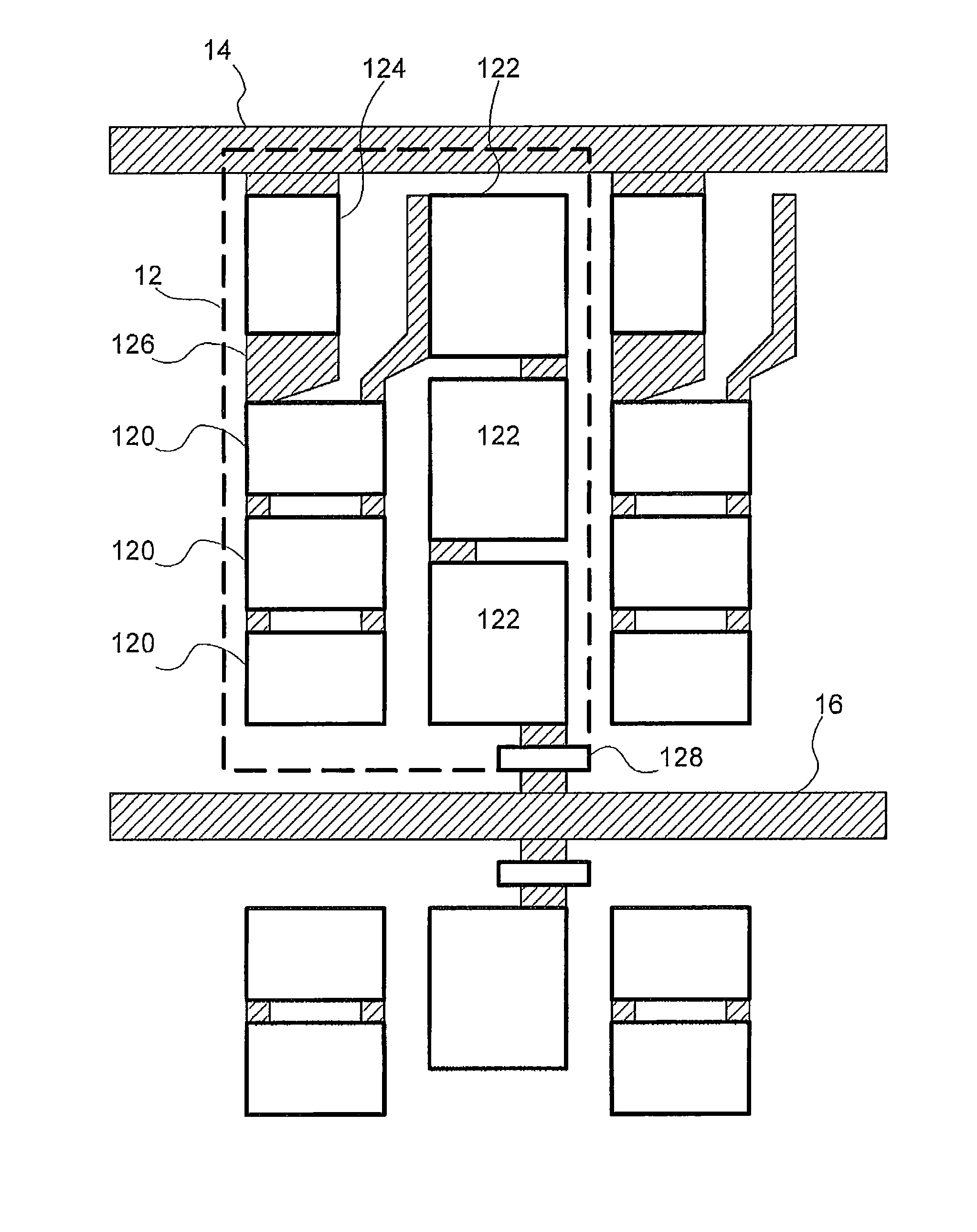
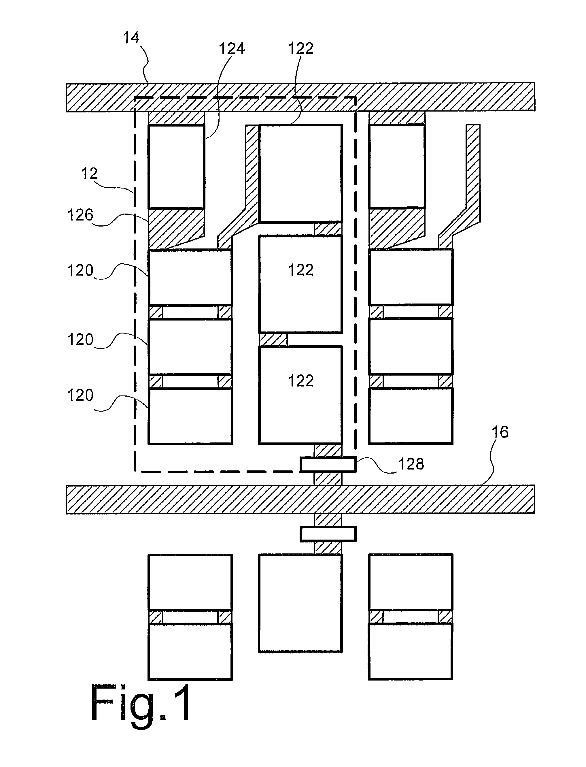
[0031]FIG. 1 shows part of an intrinsically safe LED display device, comprising a mounting board with an array of LED circuit cells 12 and power supply lines 14, 16. Each LED circuit cell 12 comprises a group of resistors 120, a group of LEDs 122, a switching type PTC 124. In each LED circuit cell 12 the group of resistors 120, the group of LEDs 122, the switching type PTC 124 are connected in series between power supply lines 14, 16. An electronic switch 128 is provided in series with this series arrangement. The electronic switch may have a control electrode (not shown) connected to a driver circuit (not shown). In another embodiment the electronic switch 128 may be shared by the series arrangements of different LED circuit cells, or it may be provided for one series arrangement only.

[0032]The array of LED circuit cells may be a two-dimensional matrix with rows and columns. Herein each LED circuit cell may form a different pixel. An image can be displayed by controlling the LED ce...


PUM


Abstract

An intrinsically safe LED display device with an array of LED circuit cells is provided. Each cell comprises a LED or a group of LEDs, which are individually made intrinsically safe in a conventional way, by limiting a dissipated power through the LED circuit cell by means of a resistor or group of resistors in series with the LED or group of LEDs. In addition a switching type PTCs with a switching temperature between 80 and 125 degrees centigrade are added in each cell, in series with the resistors or group of resistors of the LED circuit cells respectively, in thermal contact with the resistor or group of resistors of the LED circuit cell. In this way intrinsic safety is provided for mutual heating of adjoining LED circuit cells wherein the LEDs or groups of LEDs are short circuited.

Description

CROSS-REFERENCE TO RELATED APPLICATIONS[0001]This application is a 35 USC §371 U.S. national stage filing of International Patent Application No. PCT / NL2011 / 050660 filed on Sep. 29, 2011, which claims priority under the Paris Convention and 35 USC §119 to Netherland Patent Application No. 2005418, filed on Sep. 29, 2010.FIELD OF THE DISCLOSURE[0002]The invention relates to an intrinsically safe (I.S.) LED display device with an array of LEDs that is designed to provide intrinsic safety in potentially explosive environments.BACKGROUND OF THE DISCLOSURE[0003]LED display devices with arrays of LEDs have daylight display capabilities and are able to provide for relatively large displays that can be read from a distance at industrial sites.[0004]Intrinsic safety (I.S.) is a design requirement in the art, used for electronic equipment for use at industrial sites such as oil terminals and mines, where normal operating conditions or spilling may give rise to the presence of inflammable or e...

Claims


Application Information

Patent Timeline
Patent Type & Authority Patents(United States)
IPC IPC(8): H05B33/08G09G3/32H05B44/00
CPCH05B33/0887H05B33/089H05B33/0821G09G2330/045G09G3/32H05B45/40H05B45/56H01L27/156H01L25/0753G09G2320/041
Inventor TOTH, FERENCZ NANDOR
Owner EURON INTELLIGENCE
Learn More