LED driver circuit capable of adjusting output current

a driver circuit and output current technology, applied in the direction of electric variable regulation, process and machine control, instruments, etc., can solve the problems of low efficiency of the prior driver circuit, affecting the operation of the circuit, and lowering the power being supplied to the led, so as to promote the average luminance and the maximum operation power of the led, stable and proper current value, and low current noise

Inactive Publication Date: 2010-05-11
LIU DA YI
View PDF4 Cites 10 Cited by
  • Summary
  • Abstract
  • Description
  • Claims
  • Application Information

AI Technical Summary

Benefits of technology

[0005]In the prior technique, when the output voltage Vout is greater than the positive bias VLed capable of starting up the LED, the LED will light up by a driving current ILed and the value of the ILed is approximately developed in the following formula ILed=(Vout−VLed) / Rs. The power controller IC will adjust the output current according to the difference of the reference voltage Vref and the detecting voltage Vd to precisely control the luminance of the LED. Although the prior driver circuit is capable of controlling the luminance of the LED, a large part of the power is consumed by the detecting resistor Rs so that the power being supplied to the LED is lowered and thus the efficiency of the prior driver circuit is low. Besides, the power consumed by the detecting resistor Rs will transform to heat and cause a lot of disadvantageous effects to the circuit. To lower the heat issue, it is usually to lower the reference voltage and shrink the detecting resistor Rs, but the smaller the resistor is, the higher cost and higher error the resistor takes. Therefore, the cost of the driver circuit is getting higher and there are issues of precision on power supplying. For example, the error of the current control of the driver circuit will reach 10% and more because of the error of detecting resistor Rs, reference voltage, and the loss of the circuit. The current noise caused by above error will limit the performance of the LED. For example, an LED of an operation current specification of 1 A will be designed to be operated in 900 mA because of the current control issue. While using, the current being supplied to the LED is about 810 mA to 990 mA, the illuminant efficiency is serious damaged.
[0006]Accordingly, the primary object of the present invention is to provide an improved LED driver circuit which uses a differential amplified signal of voltage difference of the detecting resistor as a reference for the power controller to adjust the output voltage so as to provide a stable and proper value of current to the LED.
[0007]A secondary object of the present invention is to provide an improved LED driver circuit which is capable of lowering the current noise by the precise output current control of the differential amplifier so as to promote the average luminance and the maximum operation power of the LED.
[0008]Another object of the present invention is to provide an improved LED driver circuit which is capable of lowering the power consumption of the detecting resistor to raise the efficiency of driver circuit and avoid the high cost and high error of shrinking the detecting resistor.
[0009]A yet object of the present invention is to provide an improved LED driver circuit an output current of which is easy to be adjusted. The current specification demanded by a customer can be achieved by modifying the ratio of the resistances of a voltage detecting circuit without needing to change any circuit so that no additional design cost or manufacturing technique needs to be concerned.
[0010]A still object of the present invention is to provide an improved LED driver circuit including an adjustable resistor for adjusting the amplifying ratio of the differential amplifier. The output current can be adjusted by the needs to control the luminance of the LED.

Problems solved by technology

Although the prior driver circuit is capable of controlling the luminance of the LED, a large part of the power is consumed by the detecting resistor Rs so that the power being supplied to the LED is lowered and thus the efficiency of the prior driver circuit is low.
Besides, the power consumed by the detecting resistor Rs will transform to heat and cause a lot of disadvantageous effects to the circuit.
To lower the heat issue, it is usually to lower the reference voltage and shrink the detecting resistor Rs, but the smaller the resistor is, the higher cost and higher error the resistor takes.
Therefore, the cost of the driver circuit is getting higher and there are issues of precision on power supplying.
For example, the error of the current control of the driver circuit will reach 10% and more because of the error of detecting resistor Rs, reference voltage, and the loss of the circuit.
The current noise caused by above error will limit the performance of the LED.
While using, the current being supplied to the LED is about 810 mA to 990 mA, the illuminant efficiency is serious damaged.

Method used


Image

  • LED driver circuit capable of adjusting output current
  • LED driver circuit capable of adjusting output current
  • LED driver circuit capable of adjusting output current

Examples


Embodiment Construction

[0017]In order that those skilled in the art can further understand the present invention, a description will be provided in the following in details. However, these descriptions and the appended drawings are only used to cause those skilled in the art to understand the objects, features, and characteristics of the present invention, but not to be used to confine the scope and spirit of the present invention defined in the appended claims.

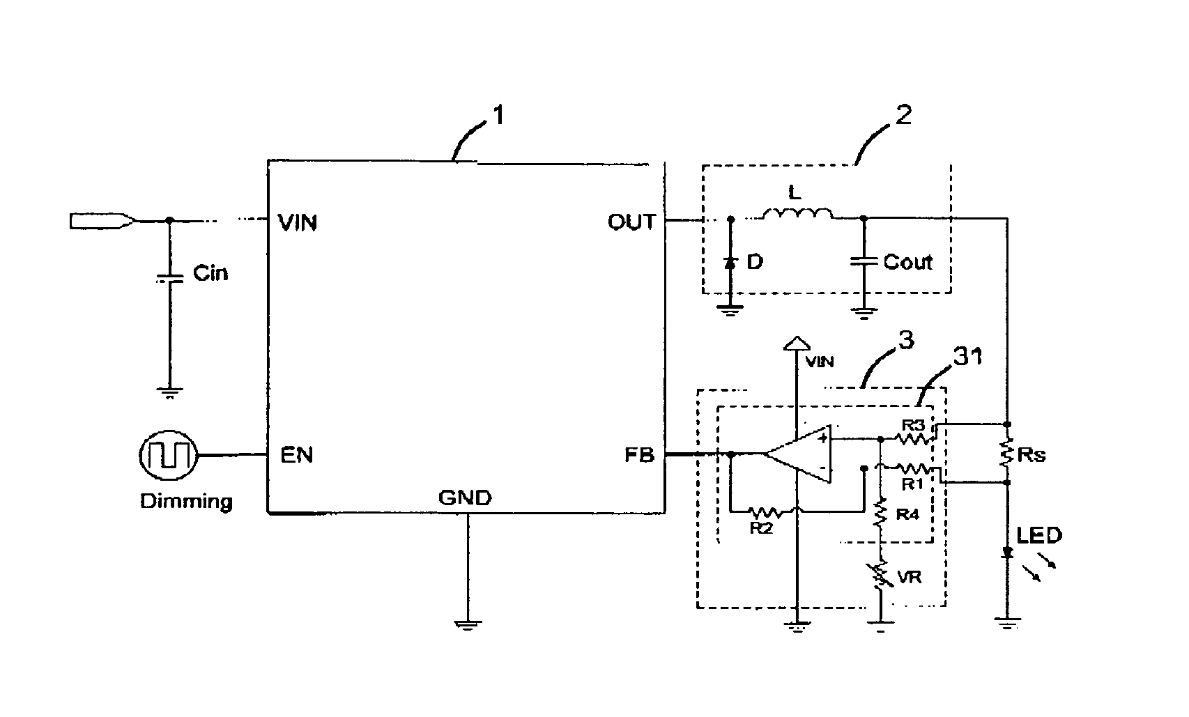
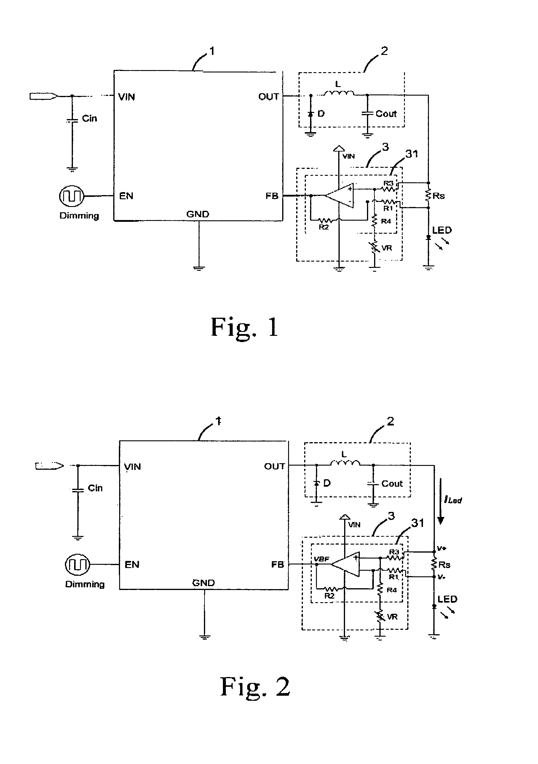
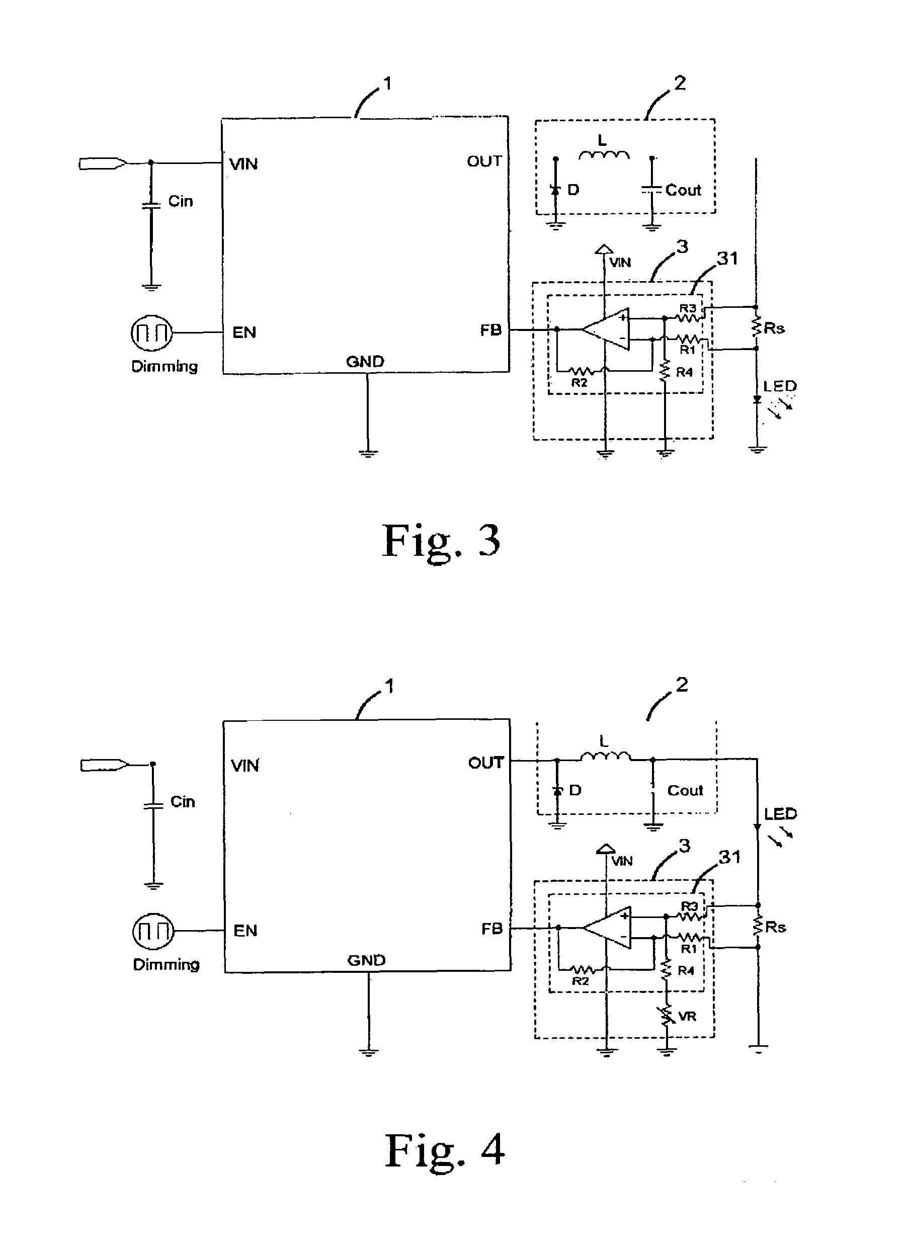
[0018]Referring to FIG. 1, a preferred embodiment of the present invention is illustrated, in that, an LED driver circuit mainly includes a power controller 1, a voltage regulator 2, a voltage detecting circuit 3, a detecting resistor Rs, and a light emitting device LED. The connection of the units is shown in FIG. 1. An input end VIN of the power controller 1 is connected to a power source. An output end of the power controller 1 is connected to the voltage regulator 2. The voltage regulator 2 connects the detecting resistor Rs and the LED. A feed...


PUM


Abstract

An LED driver circuit includes a power controller, a voltage regulator, a detecting resistor, a light emitting device, and a voltage detecting circuit. The voltage detecting circuit has a first input end connected to a higher potential end of the detecting resistor, and a second input end thereof is connected to a lower potential end of the detecting resistor. The output end of the voltage detecting circuit is connected to a feedback end of the power controller so as to output a detected voltage signal to the power controller for adjusting the output voltage and supplying a stable and proper value of current to the light emitting device. The voltage detecting circuit is a differential amplifier capable of detecting the voltage difference between the detecting resistor and amplifying it as a feedback to the power controller. Therefore, the output current from the power controller is precisely controlled.

Description

FIELD OF THE INVENTION[0001]The present invention relates to driver circuits, and in particular to an LED driver circuit capable of adjusting the output current.DESCRIPTION OF THE PRIOR ART[0002]Light Emitting Diodes (LED) has advantages of small size, low power consumption, fast light up speed, vibration resistance, long life time, and suitable for mass production. Thus, LEDs are widely used as indicators and display devices in the information, communication, and consumer electronics product, and it will be more widely used in predictable future and take the place of the traditional illuminant device. As all we knows, an LED is operated under a positive bias state, while when the bias being supplied to the LED passes the startup voltage, the LED will be conducted and thus lights up, and the luminance comes greater with the current being supplied to the LED. Usually in a practical application, a driver circuit is used to provide a stable current to maintain stable luminance of the L...

Claims


Application Information

Patent Timeline
Patent Type & Authority Patents(United States)
IPC IPC(8): H05B37/02
CPCH05B33/0815H05B45/30H05B45/37
Inventor LIU, DA-YI
Owner LIU DA YI
Why Eureka
Try Eureka