Support element for a wiper drive

a technology of support element and wiper drive, which is applied in the direction of cleaning equipment, vehicle cleaning, domestic applications, etc., can solve the problems of weakened support elements, and achieve the effect of facilitating the definition of gaps and constant width

Active Publication Date: 2016-01-05
ROBERT BOSCH GMBH
View PDF22 Cites 20 Cited by
  • Summary
  • Abstract
  • Description
  • Claims
  • Application Information

AI Technical Summary

Benefits of technology

[0008]If a load acts on the wiper drive which is sufficiently large to close the gap, an improved force transfer having reduced elasticity can thus also be achieved as a result of the contact of the support element with the surrounding structure. Said improved force transfer allows the breakage behavior of the support element to be controlled in an improved manner at the predetermined breaking point. To this end, the predetermined breaking point must not be designed for a lower load, whereby the support element would usually be weakened even during normal operation. In addition, a latency time between the introduction of the force and the breaking of the support element at the predetermined breaking point can also be reduced by the device described; thus enabling an energy absorbed by the support element to be reduced when the breaking load occurs.
[0009]In a preferred embodiment, a projection is formed on the contact portion, which projection extends in the direction of the surrounding structure. As a result, the width of the gap on the part of the support element can be determined in the unloaded state. If need be, the projection can be easily adapted in the dimensions thereof to predetermined requirements, in particular to different motor vehicles.
[0011]In a further embodiment, the projection lies off-center in the region of the contact portion in order to exert a torsional force on the support element upon contact between the support element and the surrounding structure. In addition to the bending force, the torsional force can act on the predetermined breaking point; thus enabling the breakage behavior at the predetermined breaking point to be even better controlled by means of the torsional load which does not occur during normal operation.
[0013]In one embodiment, the projection extends transversely over the entire support element. In so doing, the gap along the projection can have a constant width or decrease in size, whereby the aforementioned effect of the additional torsional force can be achieved.
[0014]The abutment region preferably lies between the predetermined breaking point and the fastening element. Effective levers at the support element, in particular with regard to the receiving portion for the wiper drive, can thus be advantageously used. In addition, the definition of the gap can be facilitated by a smaller distance between the contact region and the bearing point.
[0016]In one embodiment, an elastic element or a decoupling element is provided to engage between the bearing point and the surrounding structure. As a result, the transmission of structure-borne noise between the support element and the surrounding structure can be reduced. Furthermore, the definition of the width of the gap can simultaneously be influenced by the elasticity at the bearing point.

Problems solved by technology

To this end, the predetermined breaking point must not be designed for a lower load, whereby the support element would usually be weakened even during normal operation.

Method used


Image

  • Support element for a wiper drive
  • Support element for a wiper drive
  • Support element for a wiper drive

Examples


Embodiment Construction

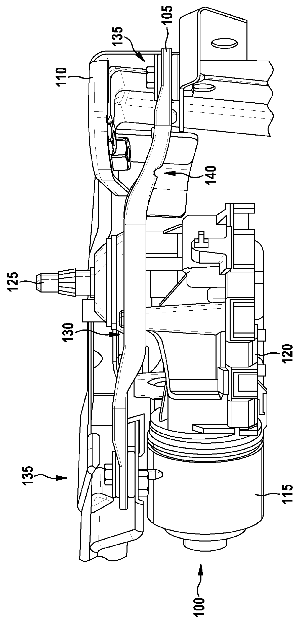
[0024]FIG. 1 shows a wiper drive 100 which is connected by means of a support element 105, a so-called board, to a body panel 110 of a motor vehicle. In alternative applications, any other surrounding structure, which typically is found on a motor vehicle in the region of a supporting structure, can also be used instead of the body panel 110. The wiper drive 100 comprises an electric motor 115, a housing 120 and a driven shaft 125. The support element 105 comprises a receiving portion 130 for attaching the wiper drive 100, at least two bearing points 135 for fixing the support element 105 to the body panel 110 and a predetermined breaking point 140. One of the bearing points 135 can be a plug-in point for insertion into a corresponding recess in the body panel 110 and another bearing point 135 can be a fixing point for fixing the support element, for example, by means of a screw or a similar means. A plurality of plug-in and / or fixing points can also be provided.

[0025]The support el...


PUM


Abstract

The invention relates to a support element (105) for a wiper drive (100), comprising a receiving portion (130) for attaching the wiper drive (100), a bearing point (135) for fixing the support element (105) to a surrounding structure (110), and a predetermined breaking point (140). A specified gap (150) lies between the support element (105) and the surrounding structure (110) at a contact portion (142) of the support element (105), the width of said gap being dependent on a force that acts on the support element (105) such that the contact portion (142) comes into contact with the surrounding structure (110) only when a specified force acting on the support element (105) is exceeded.

Description

BACKGROUND OF THE INVENTION[0001]The invention relates to a support element or a motor bracket for a wiper drive. The invention particularly relates to a support element for a wiper drive of a wiper system in a motor vehicle.[0002]A wiper system comprises a wiper arm and a wiper blade, wherein the wiper arm is set into a pivoting movement about a driven shaft by means of a wiper drive; thus enabling the wiper blade to be guided across a wiping region of a window pane. The window pane can particularly be a windshield of a motor vehicle. The wiper drive is usually attached to a body of the motor vehicle, wherein the attachment must be able to transfer forces to the body that are usual during normal operation. Besides the usual wiping forces, said forces also include peak loads, for example if the wiper blade is moved against an obstacle during wiping, when the wiper arm is being folded down onto or folded back from the window pane or within the scope of changing the wiper blade.[0003]...

Claims


Application Information

Patent Timeline
Patent Type & Authority Patents(United States)
IPC IPC(8): A47L1/00B60S1/02B60S1/04
CPCB60S1/0441B60S1/0438B60S1/0488B60S1/0444
Inventor VAN DE ROVAART, ROBERT-JANBENCSIK, BARNABAS
Owner ROBERT BOSCH GMBH
Why Eureka
Try Eureka