Swash plate type variable displacement compressor

a variable displacement compressor and swash plate technology, applied in the direction of fluid-pressure actuators, positive displacement liquid engines, servomotors, etc., can solve the problems of difficult displacement control for small actuators, difficult to create a space behind the swash plate, etc., to achieve easy expansion in size, improve mountability, and create a large space

Active Publication Date: 2016-01-05
TOYOTA IND CORP
View PDF35 Cites 22 Cited by
  • Summary
  • Abstract
  • Description
  • Claims
  • Application Information

AI Technical Summary

Benefits of technology

[0012]Accordingly, it is an objective of the present invention to provide a compressor that is compact in size and ensures improved displacement control.
[0014]When the inclination angle of the swash plate of the compressor according to the present invention is changed, the top dead center position of the second head of the piston is scarcely moved, while the top dead center position of the first head of the piston is largely moved. This allows a relatively large space to be created in a region of the swash plate chamber where the first cylinder bore is located. With reference to the swash plate, the actuator is located in the region in which the first cylinder bore is located. Thus, in the compressor, the actuator can be easily increased in size in the radial direction without increasing the size of the housing in the radial direction.
[0015]Therefore, since the compressor according to the present invention is compact, it is possible to achieve an improved mountability and ensure improved displacement control.

Problems solved by technology

Therefore, in the housing of the compressor, it is difficult to create a space behind the swash plate for allowing the non-rotational movable body and the movable body to proceed and retreat.
However, it is difficult for a small actuator to perform the displacement control.

Method used


Image

  • Swash plate type variable displacement compressor
  • Swash plate type variable displacement compressor
  • Swash plate type variable displacement compressor

Examples


first embodiment

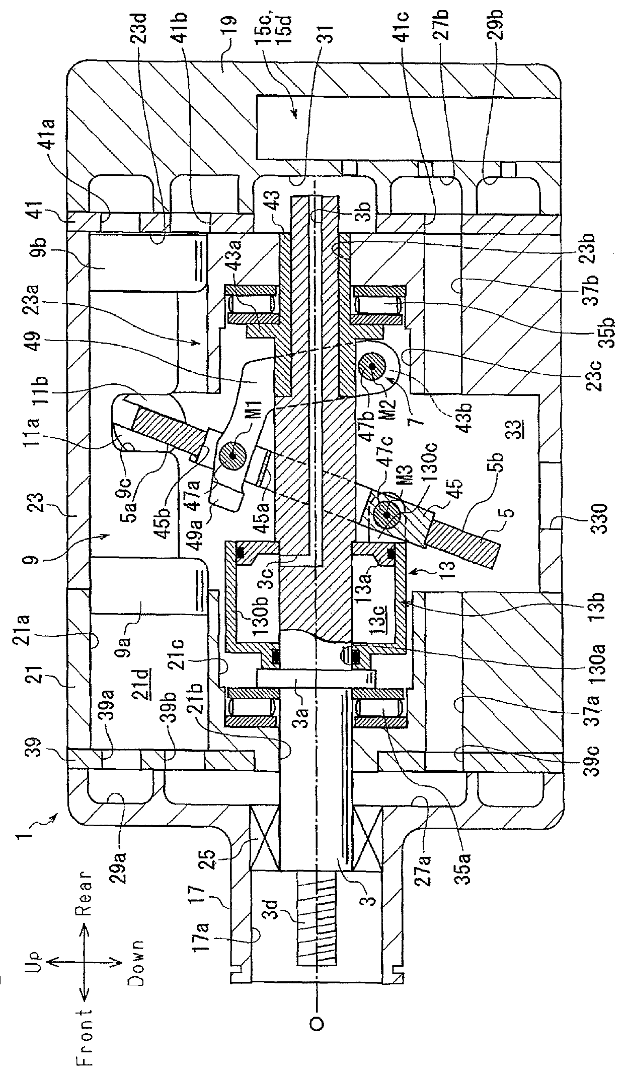
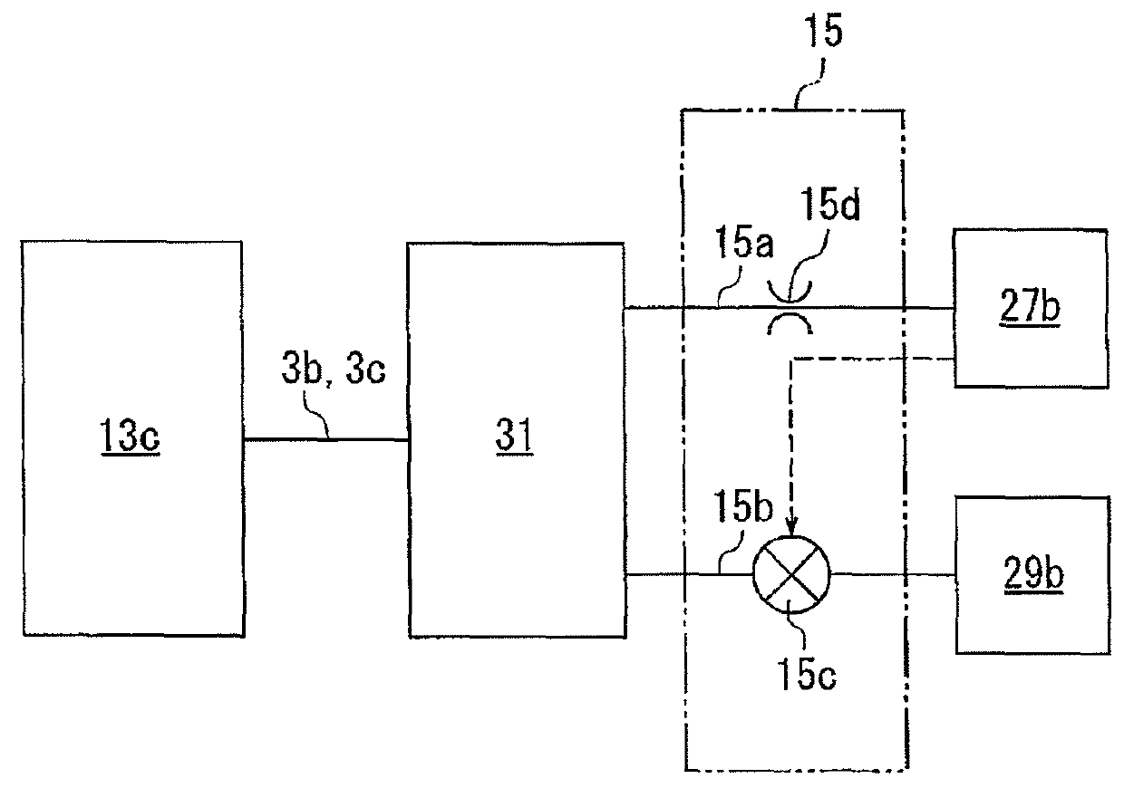
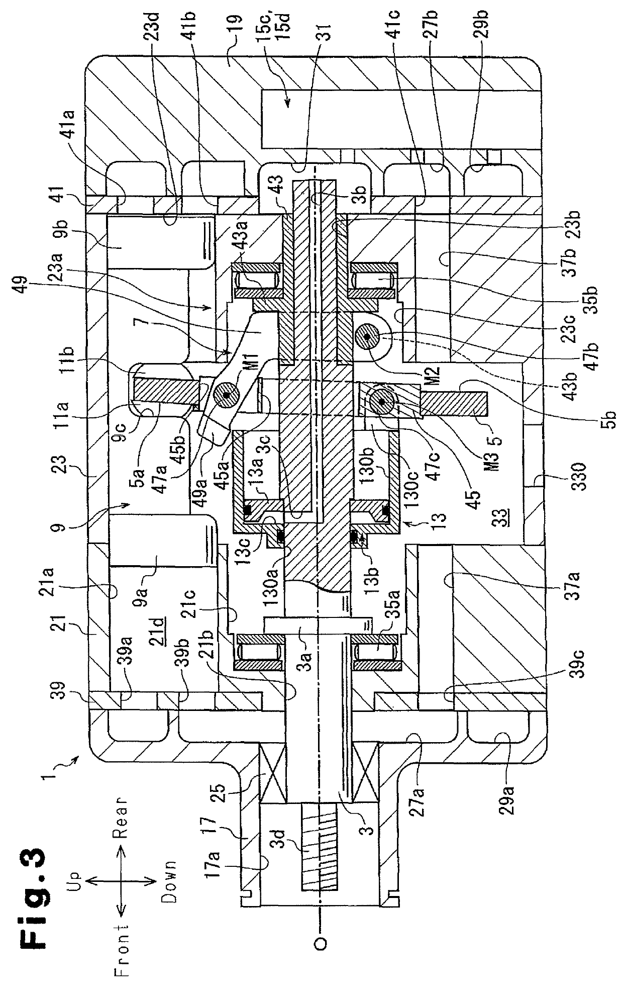
[0021]As shown in FIGS. 1 and 3, a compressor according to a first embodiment of the invention includes a housing 1, a drive shaft 3, a swash plate 5, a link mechanism 7, a plurality of pistons 9, pairs of front and rear shoes 11a, 11b, an actuator 13, and a control mechanism 15, which is illustrated in FIG. 2.

[0022]With reference to FIG. 1, the housing 1 has a front housing member 17 at a front position in the compressor, a rear housing member 19 at a rear position in the compressor, and a first cylinder block 21 and a second cylinder block 23, which are arranged between the front housing member 17 and the rear housing member 19.

[0023]The front housing member 17 has a boss 17a, which projects forward. A shaft sealing device 25 is arranged in the boss 17a and arranged between the inner periphery of the boss 17a and the drive shaft 3. A suction chamber 27a and a first discharge chamber 29a are formed in the front housing member 17. The first suction chamber 27a is arranged at a radia...

second embodiment

[0070]A compressor according to a second embodiment of the invention includes a control mechanism 16 illustrated in FIG. 4, instead of the control mechanism 15 of the compressor of the first embodiment. The control mechanism 16 includes a bleed passage 16a and a supply passage 16b each serving as a control passage, a control valve 16c, and an orifice 16d.

[0071]The bleed passage 16a is connected to the pressure regulation chamber 31 and the second suction chamber 27b. This configuration allows the bleed passage 16a to ensure communication between the control pressure chamber 13c and the second suction chamber 27b. The supply passage 16b is connected to the pressure regulation chamber 31 and the second discharge chamber 29b. The control pressure chamber 13c and the pressure regulation chamber 31 thus communicate with the second discharge chamber 29b through the supply passage 16b. The orifice 16d is formed in the supply passage 16b to restrict the amount of the refrigerant gas flowin...


PUM


Abstract

A compressor includes an actuator. The actuator is arranged in a swash plate chamber, while being rotational integrally with a drive shaft. With reference to the swash plate, the actuator is located in a region in which a first cylinder bore is located. The actuator includes a rotation body fixed to the drive shaft, a movable body, and a control pressure chamber. A link mechanism is located between the drive shaft and the swash plate. As the inclination angle of the swash plate is changed, the link mechanism moves the top dead center position of a first head by a greater amount than the top dead center position of a second head.

Description

BACKGROUND OF THE INVENTION[0001]The present invention relates to a swash plate type variable displacement compressor.[0002]Japanese Laid-Open Patent Publications No. 2-19665 and No. 5-172052 disclose conventional swash plate type variable displacement type compressors (hereinafter, referred to as compressors). The compressors include a suction chamber, a discharge chamber, a swash plate chamber, and a plurality of cylinder bores, which are formed in a housing. A drive shaft is rotationally supported in the housing. The swash plate chamber accommodates a swash plate, which is rotatable through rotation of the drive shaft. A link mechanism, which allows change of the inclination angle of the swash plate, is arranged between the drive shaft and the swash plate. The inclination angle is defined with respect to a line perpendicular to the rotation axis of the drive shaft.[0003]Each of the cylinder bores accommodates a piston in a reciprocal manner and thus forms a compression chamber. E...

Claims


Application Information

Patent Timeline
Patent Type & Authority Patents(United States)
IPC IPC(8): F04B27/10F04B27/12F04B27/18
CPCF04B27/18F04B27/12F04B27/1072F04B2027/1813F04B27/08F15B9/04
Inventor YAMAMOTO, SHINYASUZUKI, TAKAHIROHONDA, KAZUNARINISHII, KEIYAMAZAKI, YUSUKEOTA, MASAKI
Owner TOYOTA IND CORP
Why Eureka
Try Eureka