Connector assembly and method for using

a technology of connecting parts and connectors, applied in the direction of coupling device details, coupling device connections, contact members penetrating/cutting insulation/cable strands, etc., can solve the problems of unreliable electrical connection, time-consuming, labor-intensive, and difficulty in providing reliable electrical connection between separately manufactured products, and achieve the effect of quick electrical connection

Active Publication Date: 2016-01-05
R A PHILLIPS INDS
View PDF22 Cites 3 Cited by
  • Summary
  • Abstract
  • Description
  • Claims
  • Application Information

AI Technical Summary

Benefits of technology

[0007]Embodiments of the present invention provide a connector assembly that allows for a quick electrical connection when compared to other techniques and products for splicing wires.
[0016]A ridge may be at a bottom of the channel and may extend in a direction substantially perpendicular to a length direction of the channel to reduce lateral motion of the sealing material within the channel.

Problems solved by technology

In many instances, providing a reliable electrical connection between separately manufactured products can be difficult, time consuming, labor intensive, and may require specialized skills or equipment.
This method, however, typically requires multiple tools and additional materials (e.g., to strip the insulating material and solder the wires together), is relatively time consuming, the electrical connection may be unreliable if not formed properly.
Additionally, merely soldering or twisting the wires together may result in a mechanical and electrical connection that is prone to breaking, vulnerable to environmental contaminants and water exposure, and aesthetically unattractive.

Method used


Image

  • Connector assembly and method for using
  • Connector assembly and method for using
  • Connector assembly and method for using

Examples


Embodiment Construction

[0038]Embodiments of the present invention will now be described more fully with reference to the accompanying drawings, in which exemplary embodiments thereof are shown. The invention may, however, be embodied in many different forms and should not be construed as being limited to the embodiments set forth herein. Rather, these embodiments are provided so that this disclosure is thorough and complete, and will fully convey the concept of the present invention to those skilled in the art.

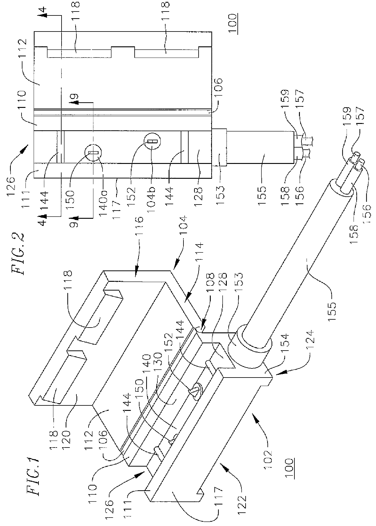
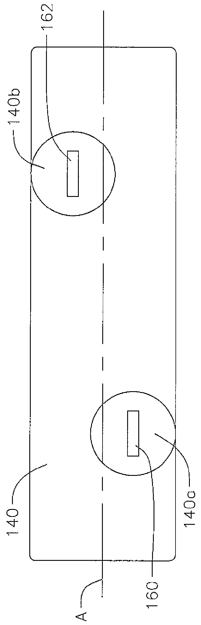
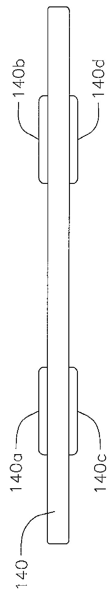
[0039]Embodiments of the present invention provide a connector assembly for quickly, efficiently, and reliably splicing wires of electrical components or products together. In particular, embodiments of the present invention include a rigid housing structure with a cable that extends into the housing at one end and may be electrically coupled to an external device or component at the other end. A plurality of conductive pins are electrically coupled to the cable inside the housing and extend outside...


PUM


Abstract

A connector assembly for providing electrical connection to an insulated conductive wire, the connector assembly including: a housing defining a channel for receiving the insulated conductive wire; a cover hinged to the housing and configured to close over the channel to cover the insulated conductive wire; and an electrically conductive pin having a first end in the channel and a second end in the housing beneath the channel.

Description

CROSS-REFERENCED TO RELATED APPLICATIONS[0001]This utility patent application claims the priority to and the benefit of U.S. Provisional Application Ser. No. 61 / 798,982, filed Mar. 15, 2013, and entitled Connector Assembly and Method for Using, the entire contents of which is incorporated herein by reference.BACKGROUND[0002]1. Field[0003]Embodiments of the present invention are related to a connector assembly and a method for using the same.[0004]2. Description of Related Art[0005]In a variety of applications, it is desirable to provide electrical coupling between components that are manufactured and sold as part of separate products. For example, a first manufacturer may sell an aftermarket component configured to be mounted on or used in conjunction with a product built and sold by a second manufacturer. Or a product manufacturer may produce and market add-on components that can be used with or connected to a main product to improve the functionality of the main product.[0006]In m...

Claims


Application Information

Patent Timeline
Patent Type & Authority Patents(United States)
IPC IPC(8): H01R4/24H01R13/447H01R13/50H01R13/58H01R24/28H01R103/00
CPCH01R4/24H01R13/447H01R13/501H01R13/5829H01R24/28H01R2103/00
Inventor PETERSON, THOMAS DALEGUO, ZHIMIN
Owner R A PHILLIPS INDS
Why Eureka
Try Eureka